


148 Agilent N5161A/62A/81A/82A/83A MXG Signal Generators User’s Guide
Basic Digital Operation (Option 651/652/654) Preliminary
Using Waveform Markers Preliminary
Waveform Marker Concepts
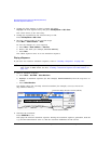
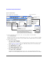
The signal generator’s Dual ARB provides four waveform markers for use on a waveform segment.
You can set each marker’s polarity and marker points (on a single sample point or over a range of
sample points). Each marker can also perform ALC hold, or RF Blanking and ALC hold.
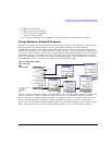
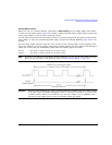
Marker Signal Response
The signal generator aligns the marker signals with the I and Q signals at the baseband generator.
However some settings such as amplitude, filters, and so forth within the RF output path can create
delays between the marker EVENT output signal and the modulated RF output. When using the
marker EVENT output signal, observe the signals (marker relative to modulated RF) for any latency,
and if needed, reset the marker point positions, include delay (page 193), or both.
Marker File Generation
Downloading a waveform file (as described in the Programming Guide) that does not have a marker
file associated with it causes the signal generator to automatically create a marker file, but does not
place any marker points.
Marker Point Edit Requirements
Before you can modify a waveform segment’s marker points, the segment must reside in BBG media
(see “Loading a Waveform Segment into BBG Media” on page 134).
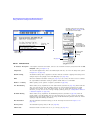
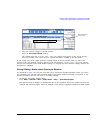
Saving Marker Polarity and Routing Settings
Marker polarity and routing settings remain until you reconfigure them, preset the signal generator,
or cycle power. To ensure that a waveform uses the correct settings when it is played, set the marker
polarities or routing (RF Blanking and ALC Hold) and save the information to the file header
(page 141).
NOTE When you use a waveform that does not have marker routings and polarity settings stored in
the file header, and the previously played waveform used RF Blanking, ensure that you set
RF Blanking to None. Failure to do so can result in no RF output or a distorted waveform.
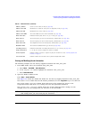
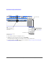
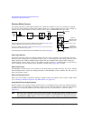
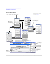
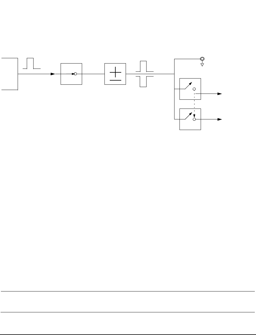
Marker
File
Bit N
Marker
Polarity
Marker N
RF Blank Off On
Marker N
Blanks RF when
Marker is Low
EVENT N
Negative
Positive
Set Marker
On Off
Marker N
ALC Hold Off On
Marker N
Holds ALC when
Marker is Low
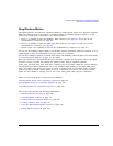
When the signal generator encounters an enabled marker (described on page 160), an
auxiliary output signal is generated and routed to the rear panel.
Event 1 is available at the EVENT 1 BNC connector (see page 19), and at a pin on the
AUXILIARY I/O connector (see page 20).
Events 2 through 4 are available at pins on the AUXILIARY I/O connector (see page 20).
RF Blank Only: includes ALC Hold