


Agilent N5161A/62A/81A/82A/83A MXG Signal Generators User’s Guide 253
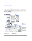
Real–Time Phase Noise Impairments (Option 432)
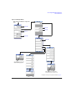
Understanding the Phase Noise Adjustments
Understanding the Phase Noise Adjustments
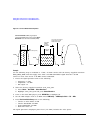
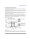
The signal generator bases the resultant phase noise shape on three settings, Lmid (amplitude), f1
(start frequency), and f2 (stop frequency).
The range for Lmid is coupled to f2, so as f2 increases in value, Lmid’s upper boundary decreases. If
the current Lmid setting is too high for the new f2 setting, the signal generator changes the Lmid
value and generates an error to alert you to the change. In addition, the actual Lmid value can vary
by 0.28 dBc/Hz from the entered value.
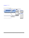
The frequency settings (f1 and f2) are really guidelines that the signal generator uses to calculate the
real frequency offset values seen on the RF OUTPUT. This means that the entered start and stop
frequency values are an approximation and may not be the values seen on a measurement
instrument, however they will be close.
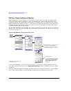
The effects of the f1 and f2 parameters are based on a varying logarithmic scale. This scale is
determined by the f2 value. The higher the f2 value the larger the scale, which makes this behavior
more noticeable at higher frequency settings. This becomes apparent when a change in the f1 or f2
value causes little to no change in the f1 or f2 position. This is easy to view using the signal
generator’s front panel phase noise graph and demonstrated in Figure 10-2. This behavior makes the
frequency adjustments coarser as the f2 frequency value increases.
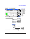
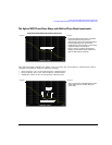
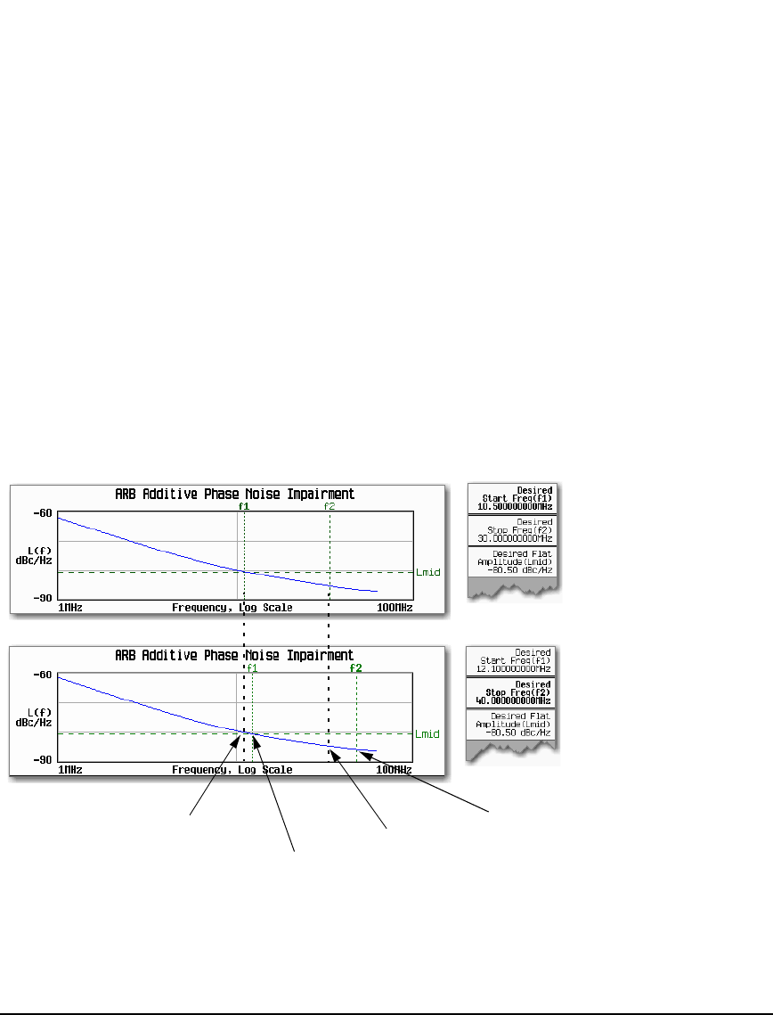
Figure 10-2 f1 and f2 Frequency Setting Behavior
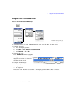
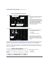
The only way to make an accurate determination of the effect of the f1 and f2 values is by viewing
the front panel graph or making a measurement. You can view the front panel graph remotely by
using the LXI interface. For more information on the LXI interface, see the Programming Guide.
f1 and f2 softkey settings for the front
panel phase noise graph.
f1 did not change frequency until
12.1 MHz was set. This means that it
took an increase of 1.6 MHz to change
its frequency offset.
f2 did not change frequency until 40
MHz was set. This means that it took an
increase of 10 MHz to change its
frequency offset.
f1—original 10.5 MHz
setting
f1—12.1 MHz setting that
moved the offset position
f2—original 30 MHz
setting
f2—40 MHz setting that
moved the offset position
For details on each key, use key help
as described on page 42.