


150 Agilent N5161A/62A/81A/82A/83A MXG Signal Generators User’s Guide
Basic Digital Operation (Option 651/652/654) Preliminary
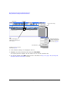
Using Waveform Markers Preliminary
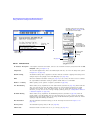
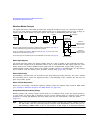
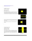
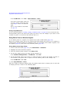
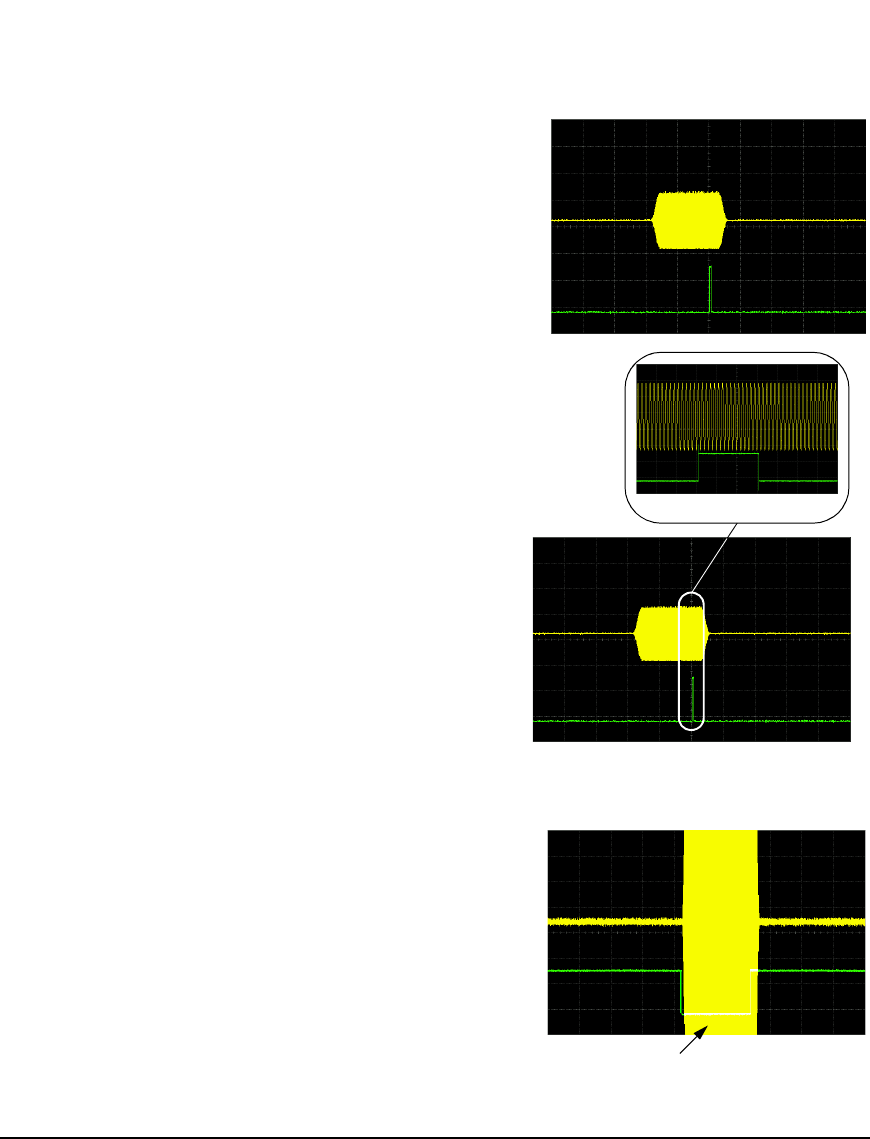
Close–up of averaging
The ALC samples the waveform when the marker signal goes
high, and uses the average of the sampled waveform to set the
ALC circuitry.
Here the ALC samples during the on marker points (positive
polarity).
Marker
Marker
Marker
Marker
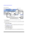
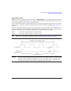
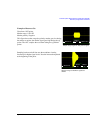
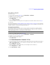
Example of Correct Use
Waveform: 1022 points
Marker range: 95–97
Marker polarity: Positive
This example shows a marker set to sample the waveform’s area of
highest amplitude. Note that the marker is set well before the
waveform’s area of lowest amplitude. This takes into account any
response difference between the marker and the waveform signal.
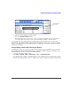
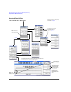
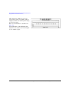
Pulse Unleveled
Example of Incorrect Use
Waveform: 1022 points
Marker range: 110–1022
Marker polarity: Positive
This example shows a marker set to sample the low part of the
same waveform, which sets the ALC modulator circuitry for
that level; this usually results in an unleveled condition for the
signal generator when it encounters the high amplitude of the
pulse.
MarkerMarker