


16 Agilent N5161A/62A/81A/82A/83A MXG Signal Generators User’s Guide
Signal Generator Overview Preliminary
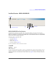
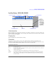
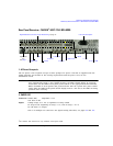
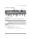
Rear Panel Overview – N5161A/62A
1
/81A/82A MXG Preliminar
3. AM
4. FM
5. PULSE
6. TRIG IN
7. TRIG OUT
Connector female BNC Impedance nominally 50 Ω
Signal An externally supplied ±1 V
p
signal that produces the indicated depth.
Damage Levels 5 V
rms
and 10 V
p
Connector female BNC Impedance nominally 50 Ω
Signal An externally supplied ±1 V
p
signal that produces the indicated deviation
Damage Levels 5 V
rms
and 10 V
p
Connector female BNC Impedance nominally 50 Ω
Signal Externally supplied: +1 V = on; 0 V = off
Damage Levels 5 V
rms
and 10 V
p
Connector female BNC Impedance high Z
Signal An externally supplied TTL or CMOS signal for triggering operations, such as point
to point in manual sweep mode or an LF sweep in external sweep mode.
Triggering can occur on either the positive or negative edge.
Damage Levels ≤ −0.5 and ≥ +5.5 V
Connector female BNC Impedance nominally 50 Ω
Signal A TTL signal that is high at the start of a dwell sequence, or when waiting for the point
trigger in manual sweep mode.
It is low when the dwell is over, or when the point trigger is received.
The logic polarity can be reversed.
This is a multiple use connector. For signal routing selections, see pages 50 and 121.