


Agilent N5161A/62A/81A/82A/83A MXG Signal Generators User’s Guide 15
Preliminary Signal Generator Overview
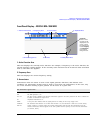
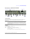
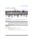
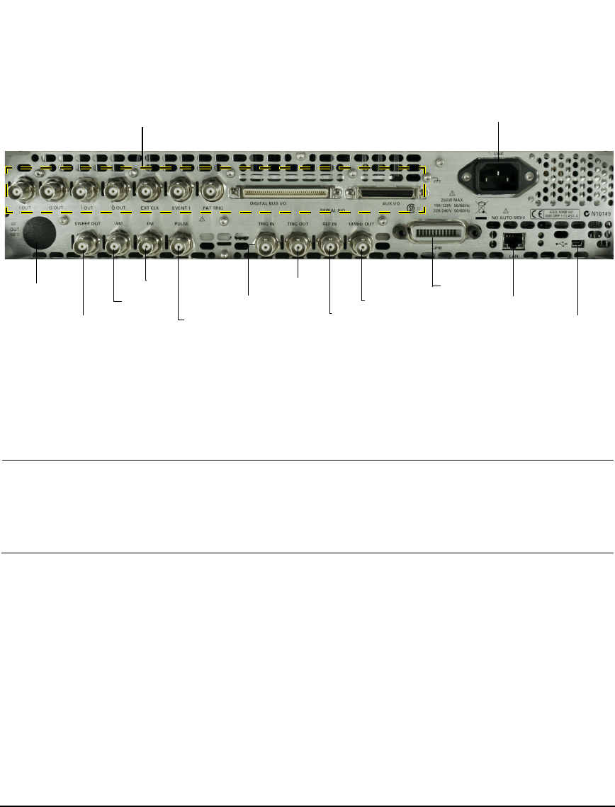
Preliminary Rear Panel Overview – N5161A/62A
1
/81A/82A MXG
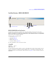
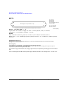
Rear Panel Overview – N5161A
1
/62A
1
/81A/82A MXG
1. AC Power Receptacle
The AC power cord receptacle accepts a three–pronged AC power cord that is supplied with the
signal generator. For details on line setting requirements and the power cord, see the
Installation Guide.
CAUTION To avoid the loss of data, GPIB settings, or current user instrument states that have not
been permanently saved to non-volatile memory, the MXG should always be powered
down either via the MXG's front panel power button or the appropriate SCPI command.
MXG's installed in rack systems and powered down with the system rack power switch
rather than the MXG's front panel switch display a Error -310 due to the MXG not being
powered down correctly.
2. SWEEP OUT
1
The N5161A and N5162A are only available with Option 1EM.
Connector female BNC
Can drive 2 kΩ.
Impedance <1 Ω
Signal Voltage range: 0 to +10 V, regardless of sweep width
In swept mode: beginning of sweep = 0 V; end of sweep = +10 V
In CW mode: no output
This is a multiple use connector. For signal routing selections, see pages 50 and 121.
2. SWEEP OUT
4. FM
5. PULSE
6. TRIG IN
7. TRIG OUT
8. REF IN
10. GPIB
11. LAN
12. Device USB
9. 10 MHz OUT
1. AC Power Receptacle
Option 1EM
only
See page 7
Digital Modulation Connectors (Vector Models Only) on page 18