


Agilent N5161A/62A/81A/82A/83A MXG Signal Generators User’s Guide 111
Preliminary Optimizing Performance
Preliminary Using Free Run, Step Dwell, and Timer Trigger
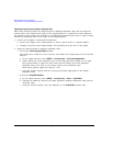
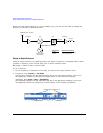
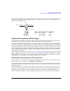
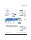
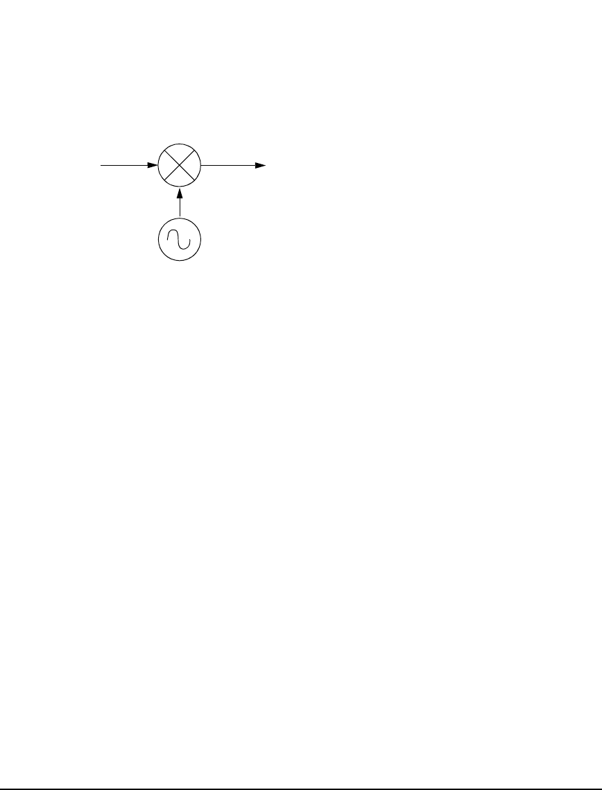
When measuring mixers, the frequency multiplier and frequency offset are often used together. In the
upconverter example below, the multiplier is set to −1 and the offset is set to 3 GHz so that the
signal generator displays f
RF
.
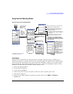
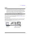
Using Free Run, Step Dwell, and Timer Trigger
Free Run, Step Dwell (time), and Timer Trigger can be used to adjust the time spent at any point in
a Step Sweep or a List Sweep. There are two possible measurement combinations:
Free Run with Step Dwell time (Figure 5- 21 on page 112) the signal generator waits for the signal to
settle and then waits for the Step Dwell time, then it jumps to the next frequency point. In addition,
the time to complete the entire sweep can vary. There is always a minimum value of Step Dwell for
each frequency point. The minimum Step Dwell timing for any point is fixed at a value of 100 us. The
time between frequency points is the sum of the settling time, plus the Step Dwell time. The settling
time is dependent on frequency, amplitude, band crossings, and other factors, so the time between
frequency points can vary.
Timer Trigger instead of Free Run (Figure 5-21 on page 112) the signal generator generates equally
spaced triggers, and it moves to the next point at each trigger. This has the advantage that the time
between points is consistent and the overall sweep time is consistent. But, if the trigger is too fast,
the signal may not have time to settle before jumping to the next point.
Understanding Free Run, Step Dwell, and Timer Trigger Setup
If the signal is to be settled for a minimum specific time at each point and it is not important if the
point to point time is consistent, use Free Run and Set Dwell time.
If the signal’s point to point time requires consistency but the specific settling time at each point can
vary, then use the Timer Trigger. Avoid using too fast of a sweep which does not allow the signal
generator to settle.
If the signal needs to be settled for a specific minimum time and consistent point to point time is
required, then you should set the Timer Trigger to be the sum of the switching time (900 us or 5 ms,
depending on options) plus the minimum settled time that is needed to make the measurement.
If the measurement requires external equipment synchronization, consider using hardware triggers.
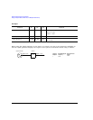
Mixer
Signal Generator
(local oscillator)
f
LO
= 800 − 600 MHz
f
IF
= 3000 MHz
Selected
Multiplier
−1
−1
Signal Generator
Output (f
LO
)
800 MHz
600 MHz
f
RF
= 2200 – 2400 MHz
Selected
Offset
3000 MHz
3000 MHz
Entered/Displayed
Frequency
(f
RF
)
2200 MHz
2400 MHz