


8 Agilent N5161A/62A/81A/82A/83A MXG Signal Generators User’s Guide
Signal Generator Overview Preliminary
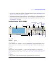
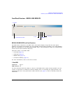
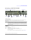
Front Panel Overview – N5181A/82A MXG Preliminar
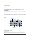
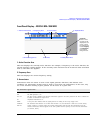
17. Q Input (vector models only)
See also, “I/Q Modulation” on page 190.
18. Knob
Rotating the knob increases or decreases a numeric value, or moves the highlight to the next digit,
character, or item in a list. See also, “Front Panel Knob Resolution” on page 28.
19. Incr Set
This hardkey enables you to set the increment value of the currently active function. The increment
value also affects how much each turn of the knob changes an active function’s value, according to
the knob’s current ratio setting (see “Front Panel Knob Resolution” on page 28).
20. Return
This hardkey enables you to retrace key presses. In a menu with more than one level, the Return key
returns to the prior menu page.
21. More and LED
When a menu contains more softkey labels than can be displayed, the More LED lights and a More
message displays below the labels. To display the next group of labels, press the More hardkey.
22. Power Switch and LEDs
This switch selects the standby mode or the power on mode. In the standby position, the yellow LED
lights and all signal generator functions deactivate. The signal generator remains connected to the
line power, and some power is consumed by some internal circuits. In the on position, the green LED
lights and the signal generator functions activate.
Connector Type: female BNC Impedance: 50 Ω
Signal An externally supplied analog, quadrature–phase component of I/Q modulation.
The signal level is = 0.5 V
rms
for a calibrated output level.
Damage Levels 1 V
rms