


Agilent N5161A/62A/81A/82A/83A MXG Signal Generators User’s Guide 101
Preliminary Optimizing Performance
Preliminary Using External Leveling (N5183A Only)
feedback for the detection circuit has been moved beyond the output attenuator. Because the
attenuator no longer affects the amplitude of the output signal, the output amplitude is determined
by only the Set ALC Level softkey.
With external leveling selected, the signal generator enables attenuator hold and the power range
approximates the range of a standard option (no attenuator) signal generator (see the Data Sheet).
As stated earlier, the actual output power may vary due to the external detector and the
coupler/power splitter performance characteristics.
NOTE When the internal detector (Internal selection) is reselected, the signal generator does not
turn the attenuator hold off.
Even though the output attenuator no longer affects the output power, it is still useful to drive the
ALC circuit to its mid–power point of approximately 0 dBm, which is optimal for the internal leveling
circuitry and typically provides the best amplitude flatness results. This is useful with negative power
values of −5 dBm or less. For example, to drive the ALC to approximately mid–power with a −20
dBm power setting, add 25 dB of attenuation. This sets the ALC circuit to 5 dBm (−20 + 25).
NOTE If there is too much attenuation, it will drive the ALC circuit too high and cause the signal
generator to go unleveled. Ensure that you decrease the attenuation as you increase the
power level.
Configure External Leveling
Basic Setup Process
• If working with a single frequency signal, perform Steps 1 through 5.
• If working with multiple frequencies:
a. Perform Steps 1 through 4.
b. Perform a user flatness correction, see “Using Flatness Correction” on page 88.
• If working with a sweep:
a. Perform Steps 1 through 4.
b. Setup the sweep, see “Configuring a Swept Output” on page 48.
1. Setup the equipment, see “Equipment Setup” on page 101
2. Configure the carrier signal, see “Configuring the Carrier” on page 102
3. Select external leveling, see “Selecting External Leveling” on page 102.
4. Determine the output amplitude range, see “Determining the Signal Generator’s Amplitude Range”
on page 102
5. Set the displayed power value, see “Adjusting the Signal Generator Display’s Amplitude Value” on
page 104
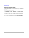
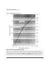
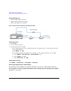
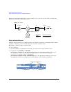
Equipment Setup
Set up the equipment as shown in Figure 5-19 on page 102. Place the external detector (detector and
coupler/power splitter) as close as possible to the DUT.