


Agilent N5161A/62A/81A/82A/83A MXG Signal Generators User’s Guide 17
Preliminary Signal Generator Overview
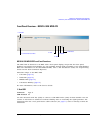
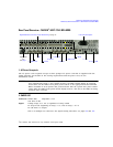
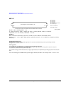
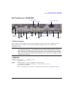
Preliminary Rear Panel Overview – N5161A/62A
1
/81A/82A MXG
8. REF IN
In its factory default mode, the signal generator can detect a valid reference signal at this connector
and automatically switch from internal to external reference operation. See “Presetting the Signal
Generator” on page 42. With Option 1ER (flexible reference input), you must explicitly tell the signal
generator the external reference frequency you wish to use; enter the information through the front
panel or over the remote interface.
9. 10 MHz OUT
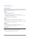
10. GPIB
This connector enables communication with compatible devices such as external controllers, and is
one of three connectors available to remotely control the signal generator (see also 11. LAN and
12. Device USB).
11. LAN
The signal generator supports local area network (LAN) based communication through this connector,
which enables a LAN–connected computer to remotely program the signal generator. The LAN
interface supports LXI; it does not support auto−MDIX. The signal generator is limited to 100 meters
on a single cable (100Base–T). For more information on the LAN, refer to the Programming Guide.
12. Device USB
Use this universal serial bus (USB) connector to connect a PC to remotely control the signal
generator.
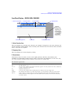
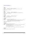
Connector female BNC Impedance nominally 50 Ω
Signal An externally supplied −3.5 to +20 dBm signal from a timebase reference that is
within ±1 ppm.
Connector female BNC Impedance nominally 50 Ω
Signal A nominal signal level greater than 4 dBm.
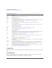
Connector Mini–B
USB Protocol Version 2.0