


Agilent N5161A/62A/81A/82A/83A MXG Signal Generators User’s Guide 7
Preliminary Signal Generator Overview
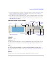
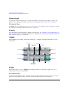
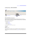
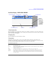
Preliminary Front Panel Overview – N5181A/82A MXG
10. Help
Use this key to display a description of any hardkey or softkey. See “Viewing Key Descriptions” on
page 42.
11. Preset and User Preset
These hardkeys set the signal generator to a known state (factory or user–defined). See “Presetting
the Signal Generator” on page 42.
12. RF Output
13. RF On/Off and LED
This hardkey toggles the operating state of the RF signal present at the RF OUTPUT connector. The
RF On/Off LED lights when RF output is enabled.
14. Mod On/Off and LED
This hardkey enables or disables the modulation of the output carrier signal by an active modulation
format. This hardkey does not set up or activate a format (see “Modulating the Carrier Signal” on
page 60).
The MOD ON/OFF LED lights when modulation of the output is enabled.
NOTE The Mod On/Off hardkey and LED functionality are only valid for MXGs with Option UNT
installed.
15. Page Down
In a table editor, use this hardkey to display the next page. See “Example: Using a Table Editor” on
page 44. When text does not fit on one page in the display area, use this key in conjunction with the
Page Up key (page 6) to scroll text.
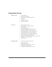
16. I Input (vector models only)
See also, “I/Q Modulation” on page 190.
Connector Standard:
Option 1EM:
Impedance:
female Type–N
Rear panel female Type–N
50 Ω
Damage Levels 50 Vdc, 2 W maximum RF power
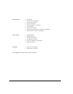
Connector Type: female BNC Impedance: 50 Ω
Signal An externally supplied analog, in–phase component of I/Q modulation.
The signal level is = 0.5 V
rms
for a calibrated output level.
Damage Levels 1 V
rms