


128 Agilent N5161A/62A/81A/82A/83A MXG Signal Generators User’s Guide
Basic Digital Operation—No BBG Option Installed
I/Q Modulation
I/Q Modulation
The following factors contribute to the error vector magnitude:
• Differences in amplitude, phase, and delay between the I and Q channels
•DC offsets
The I/Q menu provides adjustments to compensate for some of the differences in the I and Q signals
or to add impairments.
See also “Modulating the Carrier Signal” on page 60.
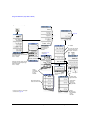
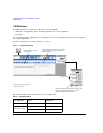
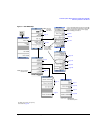
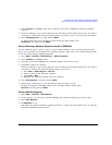
Figure 7-1 I/Q Display and Softkeys
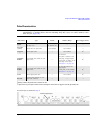
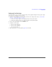
The following table shows common uses for the adjustments.
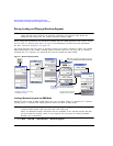
Table 7-1 I/Q Adjustments Uses
I/Q Adjustment Effect Impairment
Offset Carrier Feedthrough dc offset
Quadrature Angle
EVM error phase skew
I/Q Images I/Q path delay
This panel displays the external
I/Q signal routing.
This panel displays the current status and settings
of the I/Q adjustments. Grey text indicates I/Q
adjustments are off.
For details on each key, use key help
as described on page 42.
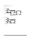
Offsets the phase of the Q signal relative to the phase of the
I signal. The quadrature adjustment key is in units of
degrees. This adjustment is not calibrated.
Sets the dc offset