


Agilent N5161A/62A/81A/82A/83A MXG Signal Generators User’s Guide 187
Preliminary Basic Digital Operation (Option 651/652/654)
Preliminary Setting the Baseband Frequency Offset
NOTE Changing the baseband frequency offset may cause a DAC over range condition that
generates error 628, Baseband Generator DAC over range. The signal generator
incorporates an automatic scaling feature to minimize this occurrence. For more information,
see “DAC Over–Range Conditions and Scaling” on page 188.
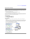
The baseband frequency offset value is one of the file header parameters (page 141), which means
you can store this value with the waveform. When you select a waveform with a stored frequency
offset value, the signal generator changes the current value to match the stored file header value. If
there is no stored baseband offset frequency value for the current waveform, the signal generator
uses the last set frequency offset value.
You can also use the Save function (page 70) to store this value as part of the signal generator setup.
When you Recall a setup stored with the Save function, the baseband frequency offset value becomes
the current instrument setting value, disregarding the stored file header value.
Use the following steps to offset the carrier from LO/carrier feedthrough. This example uses the
factory supplied waveform, SINE_TEST_WFM available in the Dual ARB Player. To view the output for
this example, connect the RF OUTPUT of the signal generator to the input of a spectrum analyzer.
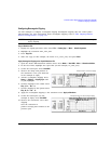
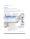
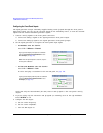
1. Select and play the waveform.
a. Press Mode > Dual ARB > Select Waveform.
b. In the Segment On BBG Media column, select SINE_TEST_WFM.
c. Press Select Waveform.
2. Generate the waveform: Press ARB Off On to On.
3. Configure the carrier signal:
a. Set the carrier signal to 1 GHz.
b. Set the amplitude to 0 dBm.
c. Turn on the RF OUTPUT.
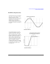
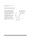
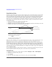
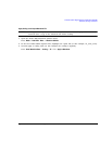
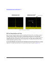
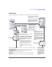
4. Press Mode > Dual Arb > ARB Setup > More > Baseband Frequency Offset > 20 MHz.
The modulated RF signal is now offset from the carrier frequency by 20 MHz as shown in the
following figures.