


10 Agilent N5161A/62A/81A/82A/83A MXG Signal Generators User’s Guide
Signal Generator Overview Preliminary
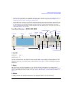
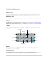
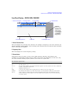
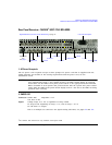
Front Panel Overview – N5161A/62A MXG ATE Preliminar
2. Power Switch and LEDs
This switch selects the standby mode or the power on mode. In the standby position, the yellow LED
lights and all signal generator functions deactivate. The signal generator remains connected to the
line power, and some power is consumed by some internal circuits. In the on position, the green LED
lights and the signal generator functions activate.
3. LAN LED
The LAN LED is used to indicate the LAN status.
• If the LED is off, the LAN is down.
• If the LED is blinking, the LAN is being configured (1.2 second duty cycle).
• A 400ms duty cycle indicates the instrument has been placed into LAN Identify mode. (Refer to
:INPut:LAN[:SET]:IDENtifier command).
• If the LED is solidly lit, the LAN is up and functional.
• If the LED fails to function, refer to the Service Guide.
4. 1588 LED
The 1588 LED indicates when the instrument is locked to an external 1588 clock.
• If the 1588 green LED is on, a 1588 signal has been detected on the TRIG OUT BNC on the rear
panel.
• If the 1588 green LED is off, no 1588 signal is detected on the TRIG OUT BNC on the rear panel.
• If the LED fails to function, refer to the Service Guide.
5. ERROR LED
The ERROR LED indicates when there are unread errors in the error queue.
• If Auto reboot is disabled, the LED will blink when an exception occurs during power up.
• If the LED fails to function, refer to the Service Guide.
6. LAN Reset Hardkey
NOTE This hardkey is enabled for fail–safe and diagnostic mode and should rarely be used.
The LAN Reset is used to access the diagnostics mode during power up.
• Refer to the SCPI Command Reference for equivalent remote commands.
• If the LAN Reset fails to function, refer to the Service Guide.