


192 Agilent N5161A/62A/81A/82A/83A MXG Signal Generators User’s Guide
Basic Digital Operation (Option 651/652/654) Preliminary
I/Q Modulation Preliminary
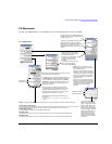
Configuring the Front Panel Inputs
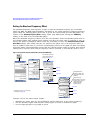
The signal generator accepts externally supplied analog I and Q signals through the front panel I
Input and Q Input. You can use the external signals as the modulating source, or sum the external
signals with the internal baseband generator signals.
1. Connect I and Q signals to the front panel connectors.
a. Connect an analog I signal to the signal generator’s front panel I Input.
b. Connect an analog Q signal to the signal generator’s front panel Q Input.
2. Set the signal generator to recognize the front panel input signals:
• To Modulate onto the Carrier
Press I/Q > I/Q Source > External.
• To Sum and Modulate onto the Carrier
Press I/Q > I/Q Source > Sum.
To select and play a waveform for the BB GEN path, see page 135.
Notice that only the internal BBG (BB GEN) routes I and Q signals to the rear panel I and Q
outputs.
3. If you are using only the external I and Q signals (no summing), turn on the I/Q modulator:
Press I/Q Off On to On.
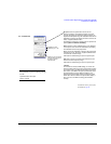
4. Configure the RF output:
a. Set the carrier frequency.
b. Set the carrier amplitude.
c. Turn the RF output on.
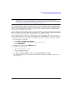
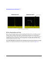
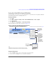
Signal generator display: both paths are calibrated
when the I/Q Correction Optimized Path is set to
Ext I/Q Output (see page 191)
Note: when the optimized path is set to RF, only the
RF Out path is calibrated.
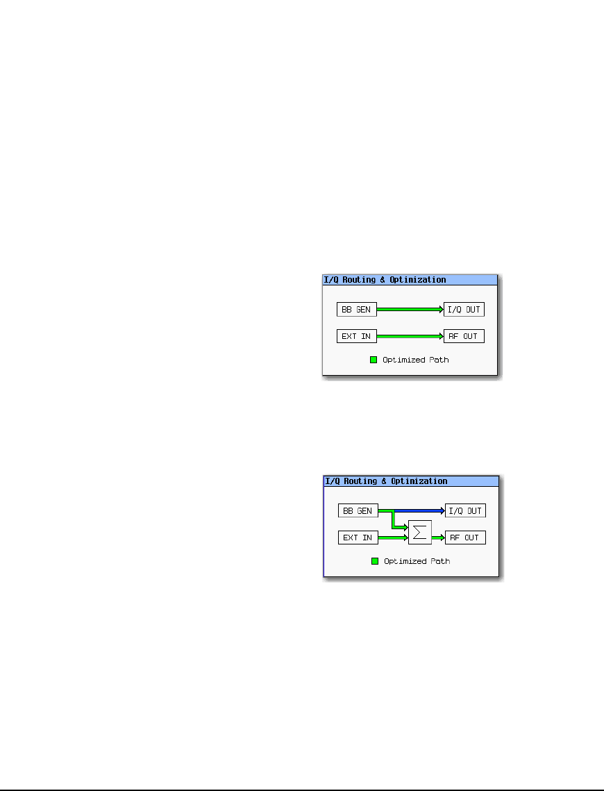
Signal generator display: both RF paths are calibrated
when the I/Q Correction Optimized Path is set to
RF Output (see page 191)