


202 Agilent N5161A/62A/81A/82A/83A MXG Signal Generators User’s Guide
Basic Digital Operation (Option 651/652/654) Preliminary
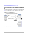
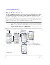
Using Finite Impulse Response (FIR) Filters in the Dual ARB Real-Time Modulation Filter Preliminary
Setting the Oversample Ratio
NOTE Modulation filters are real and have an oversample ratio (OSR) of two or greater.
Equalization filters are typically complex and must have an OSR of one (refer to “Using the
Equalization Filter” on page 196 and to “Setting the Real-Time Modulation Filter” on
page 208).
The oversample ratio (OSR) is the number of filter coefficients per symbol. Acceptable values range
from 1 through 32; the maximum number of taps allowed by the table editor is 1024.
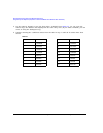
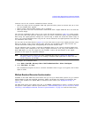
The actual limits on OSR, number of coefficients, and number of symbols depends on the feature
with which the FIR is used. Refer to Table 8-4.
For modulation filters, if the oversample ratio is different from the internal, optimally selected one,
then the filter is automatically resampled to an optimal oversample ratio.
For this example, the desired OSR is 4, which is the default, so no action is necessary.
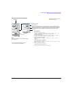
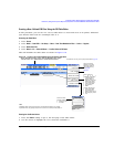
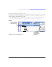
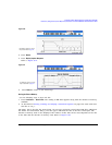
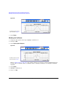
Displaying a Graphical Representation of the Filter
The signal generator has the capability of graphically displaying the filter in both time and frequency
dimensions.
1. Press More 1 of 2 > Display FFT (fast Fourier transform).
Refer to Figure 8-20 on page 203.
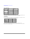
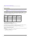
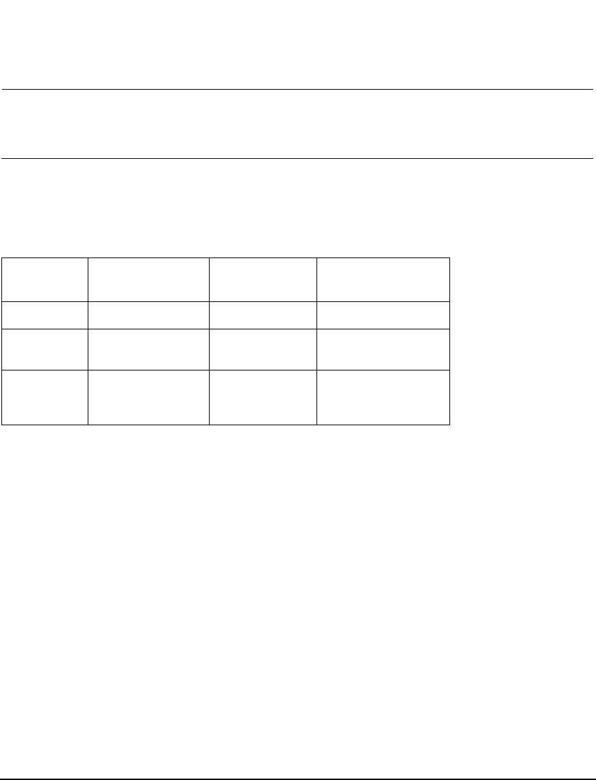
Ta b l e 8 - 4
Filter Type Oversampling Ratio
(OSR)
Number of Taps
(Maximum)
Symbols/Coefficients
(Maximum)
Equalization
a
a
When I/Q timing skew, I/Q delay, or the ACP internal I/Q channel optimization features are active, the
effective number of taps for the equalization filter are reduced.
1 256 --
ARB Custom
Modulation
b
b
The filter may be sampled to a higher or lower OSR.
≥ 2 -- 512/1024
Dual ARB
Real-Time
Modulation
c
c
The filter will be decimated to a 16 or lower OSR depending on the symbol rate.
≥ 2 -- 32/1024