


160 Agilent N5161A/62A/81A/82A/83A MXG Signal Generators User’s Guide
Basic Digital Operation (Option 651/652/654) Preliminary
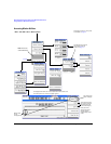
Using Waveform Markers Preliminary
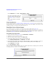
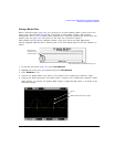
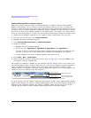
Setting Marker Polarity
Setting a negative marker polarity inverts the marker signal.
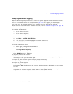
1. In second Arb menu (page 152), press Marker Utilities > Marker Polarity.
2. For each marker, set the marker polarity as desired.
• The default marker polarity is positive.
• Each marker polarity is set independently.
See also, “Saving Marker Polarity and Routing Settings” on page 148.
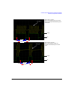
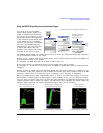
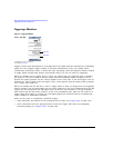
As shown on page 158:
Positive Polarity: On marker points are high (≈3.3V).
Negative Polarity: On marker points are low (0V).
RF blanking always occurs on the low part of the signal regardless of the polarity setting.
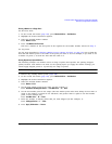
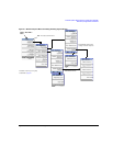
Controlling Markers in a Waveform Sequence
In a waveform segment, an enabled marker point generates an auxiliary output signal that is routed
to the rear panel EVENT output (described in “Rear Panel Overview – N5161A/62A
1
/81A/82A MXG”
on page 15) corresponding to that marker number. For a waveform sequence, you enable or disable
markers on a segment–by–segment basis; this enables you to output markers for some segments in a
sequence, but not for others. Unless you change the sequence marker settings or cycle the power, the
marker setting for the last segment edited in the sequence applies to all segments in the next
sequence that you build. For information on building a waveform sequence, see “Creating a Sequence”
on page 138.