


90 Agilent N5161A/62A/81A/82A/83A MXG Signal Generators User’s Guide
Optimizing Performance Preliminary
Using Flatness Correction Preliminary
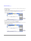
Creating a User Flatness Correction Array
In this example, you will create a user flatness correction array. The flatness correction array
contains ten frequency correction pairs (amplitude correction values for each specified frequency),
from 500 MHz to 1 GHz.
An Agilent N1911A/12A or E4419A/B power meter and E4413A power sensor are used to measure
the RF output amplitude at the specified correction frequencies and transfer the results to the signal
generator. (A U2000 Series power meter/sensor could be used in lieu of the power meter and E4413A
power sensor.) The signal generator reads the power level data from the power meter, calculates the
correction values, and stores the correction pairs in the user flatness correction array.
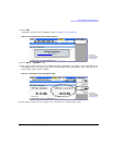
If you do not have the required Agilent power meter, or if your power meter does not have a LAN,
GPIB, or USB interface, you can enter correction values manually.
NOTE On the N5183A, if the setup is using an external leveling configuration, the equipment setup
in “Required Equipment” on page 90 assumes that the steps necessary to correctly level the
RF output have been followed. If you have questions about external leveling, refer to “Using
External Leveling (N5183A Only)” on page 97.
Required Equipment
• Agilent N1911A/12A or E4419A/B power meter (a power meter is not required with the
U2000A/01A/02A/04A Power Sensor)
• Agilent E4413A E Series CW power sensor or U2000A/01A/02A/04A Power Sensor
• GPIB, LAN, or USB interface cables, as required
• adapters and cables, as required
NOTE For operating information on a particular power meter/sensor, refer to its operating guide.
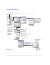
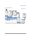
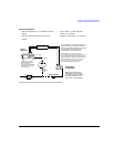
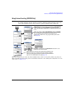
Connect the Equipment
Connect the equipment as shown in “Connect the Equipment” on page 91.
NOTE During the process of creating the user flatness correction array, the power meter is
remotely controlled by the signal generator.