


Agilent N5161A/62A/81A/82A/83A MXG Signal Generators User’s Guide 147
Preliminary Basic Digital Operation (Option 651/652/654)
Preliminary Using Waveform Markers
Using Waveform Markers
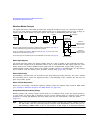
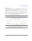
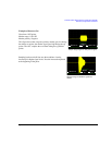
The signal generator provides four waveform markers to mark specific points on a waveform segment.
When the signal generator encounters an enabled marker, an auxiliary signal is routed to a rear
panel event output that corresponds to the marker number.
• Event 1 is available at both the EVENT 1 BNC connector (see page 19), and a pin on the
AUXILIARY I/O connector (see page 20).
• Event 2 is available at both the TRIG OUT BNC connector (see page 16), and a pin on the
AUXILIARY I/O connector (see page 20).
• Events 3 and 4 are available at pins on the AUXILIARY I/O connector (see page 20).
You can use an auxiliary output signal to synchronize another instrument with the waveform, or as a
trigger signal to start a measurement at a given point on a waveform.
You can also configure markers to initiate ALC hold or RF Blanking (which includes ALC hold). Refer
to “Using Waveform Markers” on page 147 for details.
When you download a waveform file that does not have a marker file associated with it, the signal
generator creates a marker file without any marker points. Factory–supplied segments
(RAMP_TEST_WFM and SINE_TEST_WFM) have a marker point on the first sample for all four markers.
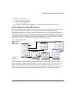
The following procedures demonstrate how to use markers while working in the dual ARB player.
These procedures also discuss two types of points: a marker point and a sample point. A marker
point is a point at which a given marker is set on a waveform; you can set one or more marker
points for each marker. A sample point is one of the many points that compose a waveform.
There are three basic steps to using waveform markers:
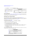
Clearing Marker Points from a Waveform Segment on page 153
Setting Marker Points in a Waveform Segment on page 154
Controlling Markers in a Waveform Sequence on page 160
This section also provides the following information:
• Waveform Marker Concepts on page 148
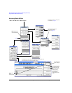
• Accessing Marker Utilities on page 152
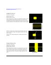
• Viewing Waveform Segment Markers on page 153
• Viewing a Marker Pulse on page 157
• Using the RF Blanking Marker Function on page 158
• Setting Marker Polarity on page 160