


94 Agilent N5161A/62A/81A/82A/83A MXG Signal Generators User’s Guide
Optimizing Performance Preliminary
Using Flatness Correction Preliminary
else
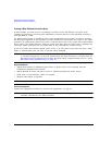
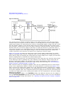
If Sockets LAN or VXI–11 LAN: Press Power Meter IP Address > power meter’s or LAN–GPIB
gateway IP address > Enter.
iii. If Sockets LAN: Press Power Meter IP Port > IP port > Enter.
else
If VXI–11: Press PM VXI–11 Device Name > device name > Enter.
When connecting directly to the power meter, enter the device name as specified in the
power meter’s documentation. Typically, this is “inst0” and is case sensitive for some
power meters. Refer to your power meter’s documentation, the Agilent Connectivity Guide
USB/LAN/GPIB Connectivity Guide (E2094–90009), and Agilent MXG’s FAQs “How do I
connect to the LAN?”
When connecting via a LAN–GPIB gateway, enter the SICL address of the power meter.
Typically, this is “gpib0,13”, where “gpib0” is the GPIB SICL interface name of the
gateway and “13” is the GPIB address of the power meter. Refer to the Agilent
Connectivity Guide USB/LAN/GPIB Connectivity Guide (E2094–90009), Agilent MXG’s FAQs
“How do I connect to the LAN?”, and to the E5810A User’s Guide or equivalent, LAN/GPIB
gateway device.
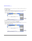
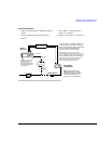
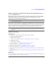
c. Open the User Flatness table editor and preset the cal array:
Press Return > Configure Cal Array > More > Preset List > Confirm Preset with Defaults.
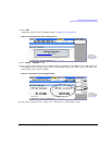
d. In the Step Array menu, enter the desired flatness–corrected start and stop frequencies, and
the number of points:
e. Populate the user flatness correction array with the step array configured in the previous
step:
Press Return > Load Cal Array From Step Array > Confirm Load From Step Data.
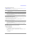
f. Set the output amplitude to 0 dBm.
g. Turn on the RF output.
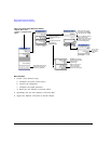
Press More > Configure Step Array >
Freq Start > 500 > MHz >
Freq Stop > 1 > GHz >
# of Points
> 10 > Enter