


162 Agilent N5161A/62A/81A/82A/83A MXG Signal Generators User’s Guide
Basic Digital Operation (Option 651/652/654) Preliminary
Using Waveform Markers Preliminary
Enabling and Disabling Markers in a Waveform Sequence
Select the waveform segments within a waveform sequence to enable or disable each segment’s
markers independently. You can enable or disable the markers either at the time of creating the
sequence or after the sequence has been created and stored. If the sequence has already been stored,
you must store the sequence again after making any changes. Enabling a marker that has no marker
points has no effect on the auxiliary outputs. To set marker points on a segment, see “Setting Marker
Points in a Waveform Segment” on page 154. This example assumes that a waveform sequence exists.
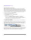
1. Ensure that all waveform segments for the sequence reside in BBG media (see page 134).
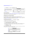
2. From the second Arb menu, press Waveform Sequences.
3. Highlight the desired waveform sequence.
4. Press Edit Selected Waveform Sequence > Enable/Disable Markers.
5. Toggle the markers:
a. Highlight the first waveform segment.
b. As desired, press Toggle Marker 1, Toggle Marker 2, Toggle Marker 3, and Toggle Marker 4.
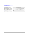
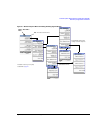
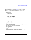
An entry in the Mkr column (see figure below) indicates that the marker is enabled for that
segment; no entry in the column means that all markers are disabled for that segment.
c. In turn, highlight each of the remaining segments and repeat Step b.
6. Press Return > More > Name and Store.
7. Either rename the sequence using the text entry keys (see page 135) or just press Enter to save
the sequence with the existing name.
The markers are enabled or disabled per the selections, and the changes saved to the sequence file.
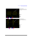
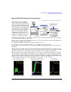
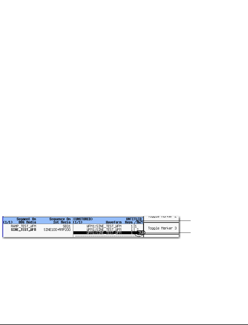
The following figure shows a sequence built using one of the factory–supplied waveform segments; a
factory–supplied segment has a marker point on the first sample for all four markers. In this
example, marker 1 is enabled for the first segment, marker 2 is enable for the second segment, and
markers 3 and 4 are enabled for the third segment.
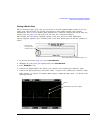
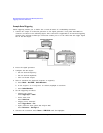
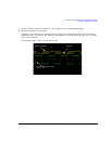
For each segment, only the markers enabled for that segment produce a rear panel auxiliary output
signal. In this example, the marker 1 auxiliary signal appears only for the first segment, because it is
disabled for the remaining segments. The marker 2 auxiliary signal appears only for the second
segment, and the marker 3 and 4 auxiliary signals appear only for the third segment.
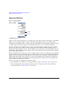
Sequence marker column
This entry shows that markers
3 and 4 are enabled for this
segment.