


102 Agilent N5161A/62A/81A/82A/83A MXG Signal Generators User’s Guide
Optimizing Performance Preliminary
Using External Leveling (N5183A Only)Preliminary
Recommended Equipment
• Agilent 8474E negative detector
• Agilent 87301D directional coupler
• cables and adapters, as required
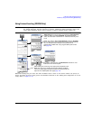
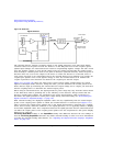
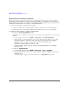
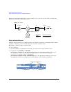
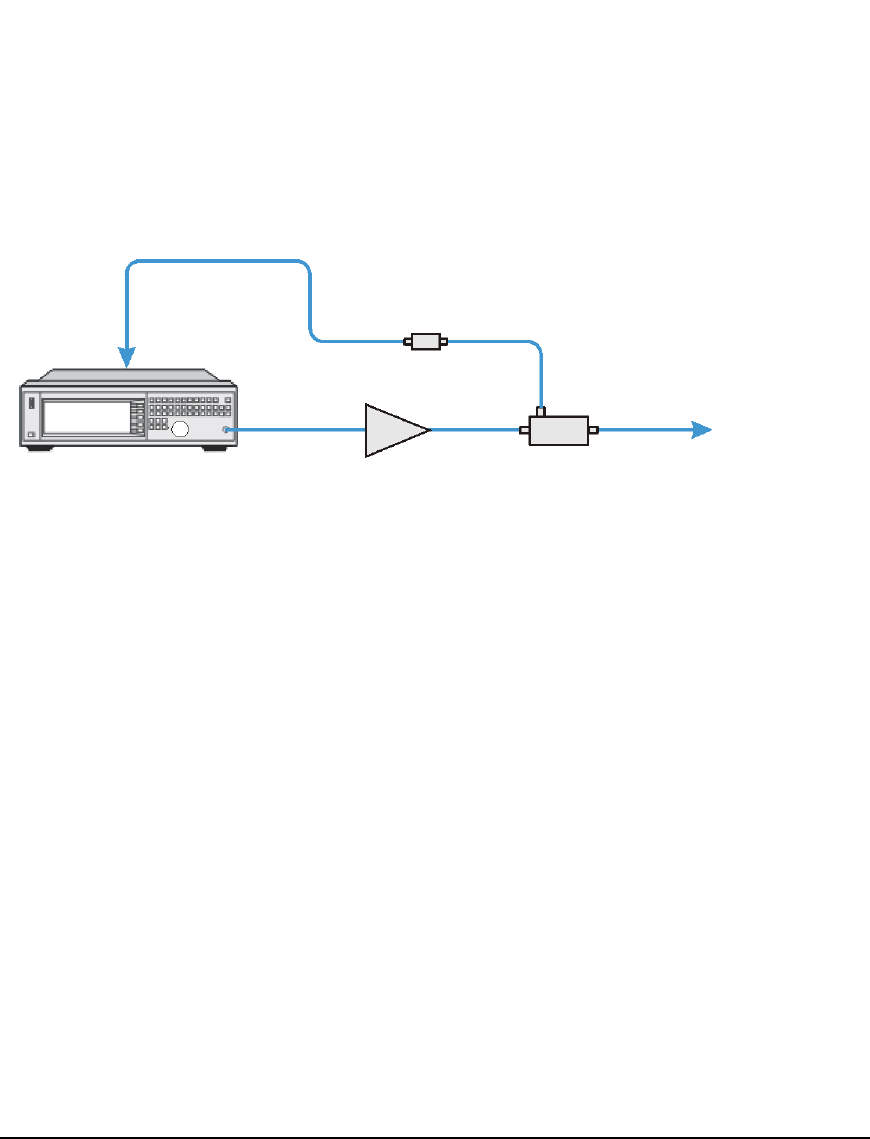
Figure 5-19 Typical External Leveling Setup using a Directional Coupler
Configuring the Carrier
1. Press Preset.
2. Set the carrier frequency.
3. Set the power level to 0 dBm:
• If the signal generator has no output attenuator (no Option 1E1) or it has Options 1E1 and
532 or 540 installed:
Press AMPTD > 0 > dBm.
• If the signal generator has Options 1E1 and 520, set the output attenuator to zero dBm:
a. Press AMPTD > Atten/ALC Control > Atten Hold Off On to On.
b. Press Set Atten > 0 > dB.
c. Press Set ALC Level > 0 > dBm.
Selecting External Leveling
Press AMPTD > Leveling Control > Leveling Mode > Ext Detector.
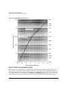
Determining the Signal Generator’s Amplitude Range
The maximum output amplitude is frequency dependent. So if you are using multiple frequency
points and there is a need to know the maximum output amplitude for each frequency point, refer to
the “Amplitude” section of the MXG Data Sheet. Then use this procedure to determine the maximum
amplitude for each band.
Leveled Signal
Signal Generator
Coupler
Amplifier
Negative Detector
RF OUTPUT
ALC INPUT