


216 Agilent N5161A/62A/81A/82A/83A MXG Signal Generators User’s Guide
Basic Digital Operation (Option 651/652/654) Preliminary
Understanding Option 012 (LO In/Out for Phase Coherency) with Multiple Baseband Generator Synchronization Preliminary
Understanding Option 012 (LO In/Out for Phase Coherency) with Multiple
Baseband Generator Synchronization
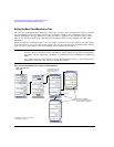
NOTE This section assumes that the previous section on Multiple Baseband Generator
Synchronization has been read and understood. If not, refer to “Multiple Baseband Generator
Synchronization” on page 209 before continuing.
The MXG with Option 012, enables 2x2, 3x3, or 4x4 MIMO configurations to share a common external
LO signal to create a phase coherent system (refer also, to “Multiple Baseband Generator
Synchronization” on page 209).
RF phase coherency may not be needed for general STC/MIMO receiver testing, since a MIMO receiver
perceives any phase differences between the sources as part of the channel conditions and correct for
them. But, RF phase coherency might be desirable for certain applications such as R&D on
beamforming systems.
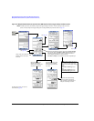
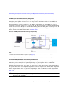
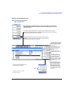
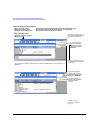
Configuring the Option 012 (LO In/Out for Phase Coherency) with MIMO
The Agilent BNC cable, part number 10502A, is the recommended cable for the standard multi–BBG
synchronization setup, and is recommended for Option 012 too (see also Figure 8-29 on page 213).
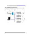
Additionally, for the 2x2, 3x3, and 4x4 MIMO connections from the LO IN and LO OUT to the splitter,
additional cables are required (refer to Table 8-5, Figure 8-30 on page 218, and Figure 8-31 on
page 219).
NOTE Agilent recommends the LO Output be covered when not in use.
When the LO In/Out jumper cable is removed and the instrument is in Dual ARB mode, the
instrument is unleveled and the instrument displays an Unlevel error message.
All test equipment requires a 12 hour warm–up period to ensure accurate performance.
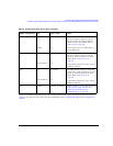
The phase coherent configuration requires the following:
• The recommended LO input drive level should be in the 0 to 6 dBm range.
NOTE The 0 to 6 dBm LO input drive level ensures the instruments will operate over the full
frequency and over the full 0 to 55 ambient temperature range
1
.
• The I/Q calibration and the self–test must be performed with the LO In/Out jumper cable in
place. Where the I/Q calibration cannot be run, the baseband offset can be manually adjusted to
minimize the I/Q offsets.
• The phase coherency feature only applies to the Dual ARB modulation mode.
• All cables from the splitter output to the instrument inputs should be of equal lengths.
1
LO input power requirements vary with temperature; power <0 dBm may work at 20–30 degree ambient
temperature conditions. Refer to the Data Sheet.