


Agilent N5161A/62A/81A/82A/83A MXG Signal Generators User’s Guide 91
Preliminary Optimizing Performance
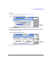
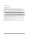
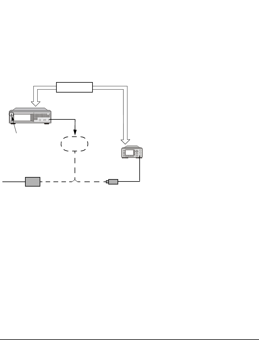
Preliminary Using Flatness Correction
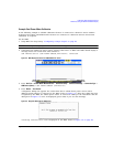
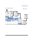
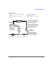
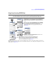
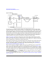
Connect the Equipment
• Agilent N1911A/12A or E4419A/B power
meter
a
• Agilent U2000A/01A/02A/04A power
Sensor
a
a
For operating information, refer to the power meter/sensor documentation.
• LAN, GPIB, or USB interface
cables, as required
• adapters and cables, as required
The LAN, GPIB*, and USB connections are
for convenience. If your power meter does
not have LAN, GPIB, or USB, then manually
enter corrections as described in the
correction entry step in this section.
*GPIB control of a power meter requires a
LAN–GPIB gateway and use of the connection type
VXI–11. Refer to the Agilent Connectivity Guide
USB/LAN/GPIB Connectivity Guide (E2094–90009),
Agilent MXG’s FAQs “How do I connect to the
LAN?”, and to the E5810A User’s Guide or
equivalent LAN/GPIB gateway device.
Power Sensor
Power Meter
(if applicable)
Signal
Generator
Device Under Test
Out
In
Input Port
RF Output
Cables
and other
Devices
Flatness
Corrected
Output
LAN/
Note: Agilent U2000 Series
USB Power Sensors connect
directly to the signal generator’s
front panel USB port (i.e. the
power meter is not applicable).
USB port for connecting
USB–compatible power
meters/sensors (e.g.
N1911A/12A Power Meters
and U2000A Series USB
Power Sensors).
GPIB
E5810A
LAN/GPIB Gateway