


98 Agilent N5161A/62A/81A/82A/83A MXG Signal Generators User’s Guide
Optimizing Performance Preliminary
Using External Leveling (N5183A Only)Preliminary
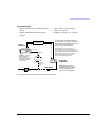
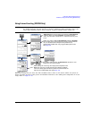
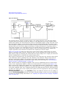
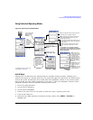
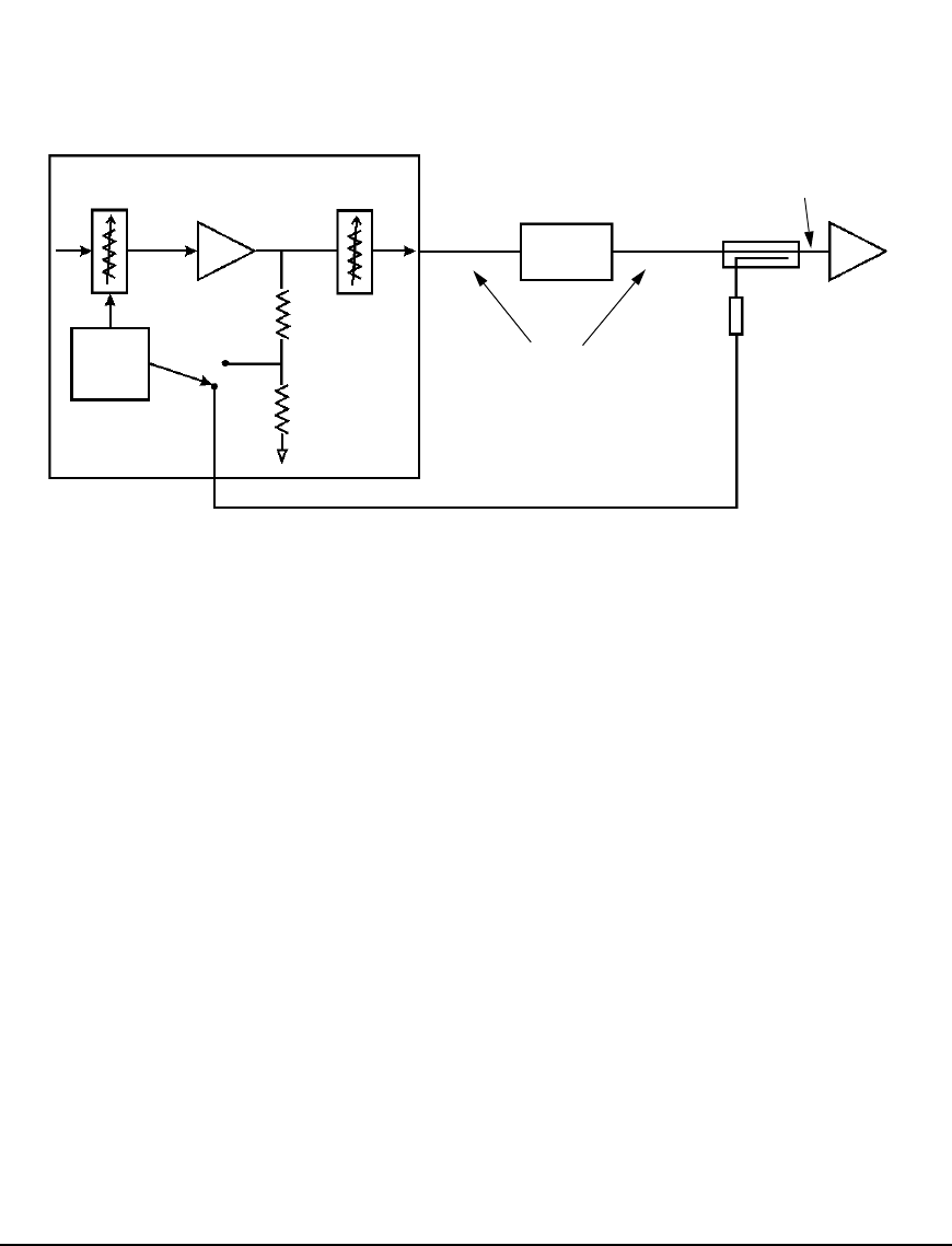
Figure 5-16 ALC Circuity
The external detector outputs a negative voltage to the signal generator’s rear panel ALC INPUT
connector based on the power level at the detector. As the RF power level at the coupler’s/power
splitter input changes, the external detector returns a compensating negative voltage. The ALC circuit
uses this negative voltage to level the RF output power by raising and lowering the signal’s power,
thus ensuring a constant power level at the point of detection (external detector). Since the point of
detection does not occur at the output of the device to which the detector is connected, there is
some power loss that is not compensated for by the external detector. For example on a coupler, the
coupled port siphons some of the signal’s energy to drive the external detector. In addition the
coupler experiences some insertion loss between the coupled port and the output.
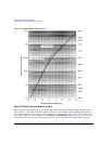
Figure 5- 18 on page 100 shows the input power versus output voltage characteristics for typical
Agilent Technologies diode detectors. Using this chart, you can determine the leveled power at the
diode detector input by measuring the external detector output voltage. For a coupler, you must then
add the coupling factor to determine the leveled output power.
When using an external detector, the signal generator’s power range may vary from the values shown
in the data sheet. This is primarily due to the efficiency of the detector. Always ensure that the
detector, coupler/power splitter are specified for the power and frequency range of interest. To
determine the signal generator’s actual power range during external leveling, see “Determining the
Signal Generator’s Amplitude Range” on page 102.
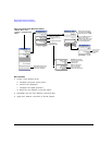
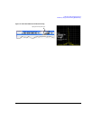
With external leveling, the displayed amplitude value can vary significantly from the actual output
power of the coupler/power splitter to which the external detector is connected (see Figure 5-17).
This is because the coupler/power splitter has it own signal characteristics (insertion loss, coupling
factor, and so forth), which are unknown to the signal generator, so it is typically unable to display
an accurate amplitude value. Also components between the signal generator and the external detector
can affect the output power of the coupler/power splitter. You can compensate for this power display
difference by using the
Ext Leveling Amptd Offset softkey or the Amptd Offset softkey. The difference between the two softkeys is
that the Ext Leveling Amptd Offset functions only while external leveling is active. For more information
on using the external leveling offset feature, see “Adjusting the Signal Generator Display’s Amplitude
Value” on page 104.
External Detector
Power Splitter
Component
DUT
RF
Cabling
OUTPUT
ALC INPUT
ALC Modulator
ALC
Internal Detector
Driver
Signal Generator
Leveled Output
(Amp, Filter,
Atten, etc.)
(Negative output)
or Coupler
Opt 1E1 Output
Attenuator
(see page 100).