


Agilent N5161A/62A/81A/82A/83A MXG Signal Generators User’s Guide 217
Preliminary Basic Digital Operation (Option 651/652/654)
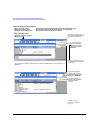
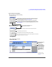
Preliminary Understanding Option 012 (LO In/Out for Phase Coherency) with Multiple Baseband Generator Synchronization
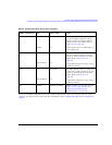
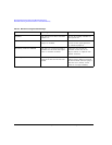
Table 8-5 Option 012 (LO In/Out for Phase Coherency) Equipment
MIMO Configuration
Part
a
a
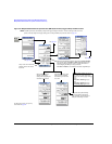
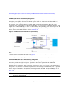
On all of the MIMO configurations, the same length of SMA flexible cables are connected from the splitter
output to the inputs on the master and slave instruments. Refer to Figure 8-30 on page 218 and to Figure 8-31 on
page 219.
Cable Length Notes
2x2 n/a
11636A
As required
n/a
SMA flexible cables are connected from
the power splitter outputs to the LO
inputs on the rear panel of both the
master and the slave MXGs. Refer to
Figure 8-30 on page 218.
Power Divider, DC to 18 GHz. Refer to
www.agilent.com.
3x3 n/a
PS3–20–451/12
S
As required
n/a
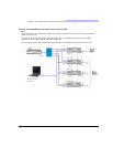
SMA flexible cables are connected from
the power splitter outputs to the LO
inputs on the rear panel of the slave
MXGs. Refer to Figure 8-31 on
page 219.
3–Way Pulser Microwave Corp., 3–Way
Wilkinson Dividers
4x4 n/a
PS4–16–452/10
S
As required
n/a
The SMA flexible cables are connected
to the power splitter output to the LO
inputs on the rear panel of the slave
MXGs. Refer to Figure 8-31 on
page 219.
4–Way Pulser Microwave Corp., 4–Way
Wilkinson Dividers
All 10502A 22.86 cm (9 inches) Refer to Figure 8-30 on page 218 and
Figure 8-31 on page 219. See also
“Multiple Baseband Generator
Synchronization” on page 209.