


Agilent N5161A/62A/81A/82A/83A MXG Signal Generators User’s Guide 269
Custom Digital Modulation (Option 431)
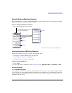
Using the Arbitrary Waveform Generator
Creating a Multicarrier Digital Modulation Setup
1. Press Preset.
2. Press Mode > ARB Custom Modulation > Multicarrier Off On to On.
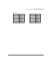
3. Press Multicarrier Setup > Select Carrier and Initialize Table > Carrier Setup > EDGE > Done.
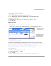
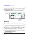
Modifying Carrier Frequency Offset
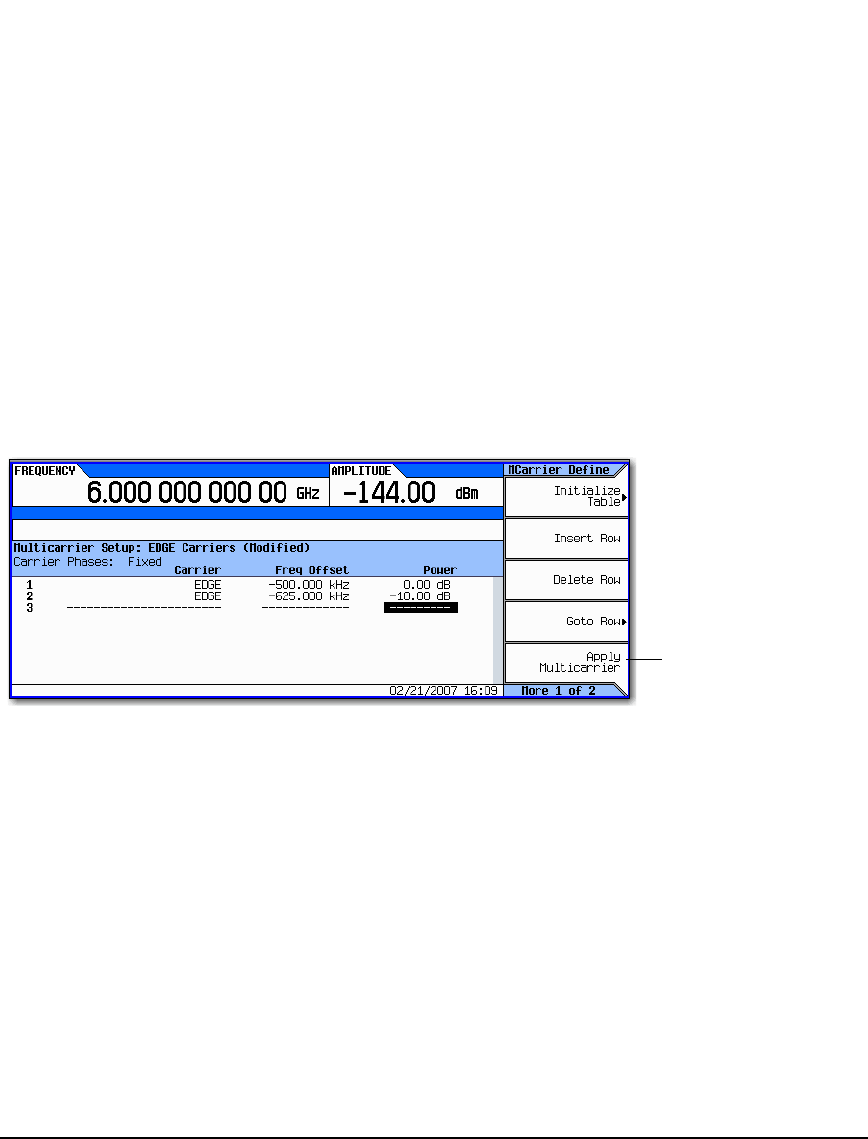
1. Highlight the Freq Offset value (500.000 kHz) for the carrier in row 2.
2. Press –625 > kHz.
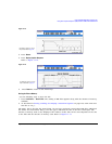
Modifying Carrier Power
1. Highlight the Power value (0.00 dB) for the carrier in row 2.
2. Press –10 > dB.
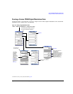
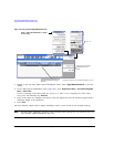
You now have a custom 2–carrier EDGE waveform with a carrier at a frequency offset of
−625 kHz and a power level of −10.00 dBm, as shown in the following figure.
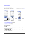
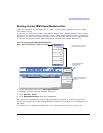
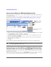
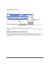
Generating the Waveform
Press Return > Digital Modulation Off On.
This generates a waveform with the custom, multicarrier, EDGE state created in the previous
sections. The display changes to Dig Mod Setup: Multicarrier (Modified). During waveform
generation, the DIGMOD and I/Q annunciators appear and the new custom, multicarrier, EDGE state
is stored in volatile memory. The waveform is now modulating the RF carrier.
For instructions on storing this custom, multicarrier, EDGE state to non–volatile memory, see
“Storing a Custom Multicarrier TDMA Digital Modulation State” on page 270.
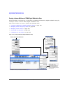
Configuring the RF Output
1. Set the RF output frequency to 890.01 MHz.
2. Set the output amplitude to −10 dBm.
3. Press RF On/Off.
The custom multicarrier EDGE signal is now available at the RF OUTPUT connector.
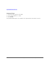
If Digital Modulation is already on, you
must press Apply Multicarrier to apply
the changes and generate a new
custom multicarrier digital modulation
waveform based on the updated
values.
For details on each key, use key
help as described on page 42.