


Agilent N5161A/62A/81A/82A/83A MXG Signal Generators User’s Guide 193
Preliminary Basic Digital Operation (Option 651/652/654)
Preliminary I/Q Adjustments
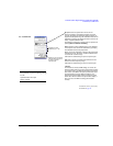
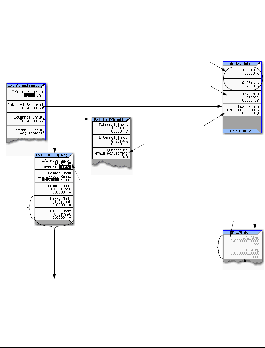
I/Q Adjustments
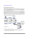
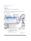
Use the I/Q Adjustments to compensate for or add impairments to the I/Q signal.
I/Q > I/Q Adjustments
Available only when a
waveform is playing.
Available only
with Option 1EL
Adjusts the I signal amplitude relative to the Q
signal amplitude. Use this as an internal
impairment, or to compensate for differences in
signal path loss that occur due to path
irregularities in the external I and Q output
cabling.
Offsets the phase of the Q signal
relative to the phase of the I signal.
The baseband quadrature
adjustment key is calibrated in units
of degrees. The external input
quadrature adjustment is not
calibrated.
The function provided by this key is
not the same as the function
provided by the I/Q Skew key.
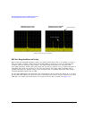
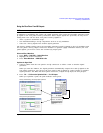
Skew is typically used either to create
impairments, or to reduce error vectors on
large bandwidth signals.
Provides a relative time delay correction
between the I and Q signals. The different
signal paths traveled by the I and Q signals
result in time delay differences that show
up as an EVM error in large bandwidth
modulated signals.
Adding an equal and opposite time delay
(skew) in the I/Q signals during baseband
generation eliminates the time delay error,
correcting for any delays in signals that are
generated in the internal baseband
generator.
Changes the absolute phase of
both the I and Q signals with
respect to triggers and markers.
Positive values add delay and
negative values advance the
signals. This value affects both
the baseband signal modulated
onto the RF and the external
output signals (I and Q). This
setting cannot be used with
constant envelope modulation
and it does not affect external I
and Q inputs.
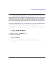
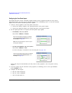
Offsets are typically used to either reduce carrier leakage, or to create an impairment that simulates carrier leakage.
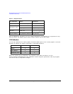
Common Mode I/Q Offset Range
This changes the adjustment range of the Common Mode I/Q Offset from Coarse (Default) to fine or vice versa. The Coarse
range corresponds to the default value of ± 2.5V. The Fine range corresponds to a value of ± 100 mV.
Common Mode I/Q Offset
This adjusts the DC offset of both I and Q signals simultaneously.
Diff Mode I Offset
This adjusts the DC offset level of the I and I–bar output signal. I and I–bar cannot be adjusted independently.
Diff Mode Q Offset
This adjusts the DC offset level of the I and I–bar output signal. I and I–bar cannot be adjusted independently.
The DC offset values are calibrated relative to
the RMS waveform voltage being played out of
the ARB. See page 144.
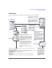
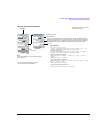
The I/Q Attenuator softkey affects the I/Q signal to the RF
Output and the External I/Q Outputs.
This softkey is active when the I/Q optimized path is set
to Ext I/Q Output and a digital modulation personality is
on. This attenuation is also adjustable using the Mod
Attenuator key located in the Arb Setup menus in each
personality. This adjustment is not affected by the I/Q
Adjustments On/Off key.
When Auto mode is selected, the signal generator
automatically optimizes I/Q attenuation for the current
conditions. When the Manual mode is selected, I/Q
Attenuation is the active function. The value you enter
sets the attenuation level of the I/Q signal.
SCPI Commands (Refer to the commands for each
personality):
[:SOURce]:RADio:<personality>:IQ:MODulatio
n:ATTen