


viii ST 3000 Release 300 and SFC Model STS103 User’s Manual 6/08
Figures
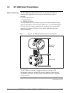
Figure 1 Typical ST 3000 Differential Pressure Transmitter................................................................................2
Figure 2 Functional Block Diagram for Transmitter in Analog Mode of Operation............................................
3
Figure 3 Functional Block Diagram for Transmitter in Digital DE Mode of Operation. .....................................
4
Figure 4 Typical SFC Communication Interface..................................................................................................
8
Figure 5 Typical ST 3000 Transmitter and SFC Order Components. ................................................................
11
Figure 6 ST 3000 with Local Smart Meter Option.............................................................................................
14
Figure 7 Typical Mounting Area Considerations Prior to Installation ...............................................................
19
Figure 8 Typical Bracket Mounted and Flange Mounted Installations...............................................................
26
Figure 9 Leveling a Model STA122 or 922 Absolute Pressure Transmitter. .....................................................
30
Figure 10 Typical Flange Mounted Transmitter Installation................................................................................
33
Figure 11 Typical Flush Mounted Transmitter Installation..................................................................................
34
Figure 12 Typical Pipe and Flange Mounted Installations ...................................................................................
35
Figure 13 Typical Remote Diaphragm Seal Transmitter Installation. ..................................................................
37
Figure 14 Typical 3-Valve Manifold and Blow-Down Piping Arrangement. ......................................................
38
Figure 15 Typical Piping Arrangement for ½” NPT Process Connection............................................................
39
Figure 16 Operating Range for ST 3000 Transmitters. ........................................................................................
43
Figure 17 ST 3000 Transmitter Terminal Block...................................................................................................
44
Figure 18 Ground Connection for Lightning Protection.......................................................................................
46
Figure 19 Typical SFC Connections.....................................................................................................................
50
Figure 20 Write Protect Jumper Location and Selections.....................................................................................
55
Figure 21 Display With All Indicators Lit............................................................................................................
56
Figure 22 Keystroke Summary for Changing Mode of Operation. ......................................................................
58
Figure 23 Summary of Configuration Process......................................................................................................
60
Figure 24 SFC and ST 3000 Transmitter Memories.............................................................................................
61
Figure 25 Flowchart — ST 3000 Pressure Transmitter Configuration.................................................................
66
Figure 26 Keystroke Summary for Entering Tag Number....................................................................................
72
Figure 27 Keystroke Summary for Selecting Output Conformity........................................................................
74
Figure 28 Square Root Dropout Points.................................................................................................................
75
Figure 29 Keystroke Summary for Adjusting Damping Time..............................................................................
77
Figure 30 Keystroke Summary for Keying in LRV and URV..............................................................................
81
Figure 31 Keystroke Summary for Setting LRV and URV to Applied Pressures................................................
83
Figure 32 Typical Setup for Setting Range Values Using Local Zero and Span Adjustments.............................
90
Figure 33 Keystroke Summary for Selecting Mode of Output Signal Indication.................................................
93
Figure 34 Keystroke Summary for Selecting Message Format. ...........................................................................
95
Figure 35 Keystroke Summary for Configuring Local Smart Meter..................................................................
102
Figure 36 Button Pushing Summary for Selecting Engineering Units. ..............................................................
120
Figure 37 Button Pushing Summary for Setting Lower and Upper Display Limits...........................................121
Figure 38 Typical SFC and Meter Connections for Constant-Current Source Mode.........................................127
Figure 39 Typical Piping Arrangement for Flow Measurement with DP Type Transmitter..............................128
Figure 40 Typical Piping Arrangement for Pressure Measurement with DP Type Transmitter.........................131
Figure 41 Typical Piping Arrangement for Liquid Level Measurement with
DP Type Transmitter and Vented Tank..............................................................................................133
Figure 42 Typical Piping Arrangement for Liquid Level Measurement with
DP Type Transmitter and Pressurized Tank.......................................................................................136
Figure 43 Typical Piping Arrangement for Pressure Measurement with GP Type Transmitter.........................140
Figure 44 Typical Piping Arrangement for Liquid Level Measurement with GP TypeTransmitter...................140
Figure 45 Typical Arrangement for Pressure Measurement with Flush Mount Transmitter..............................144
Figure 46 Typical Arrangement for Liquid Level Measurement with Flush Mount Transmitter.......................144
Figure 47 Typical Piping Arrangement for Pressure Measurement with AP Type Transmitter.........................145