


ST 3000 Release 300 and SFC Model STS103 User’s Manual 6/08
64
6.2 Overview, Continued
What to configure,
continued
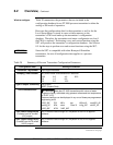
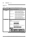
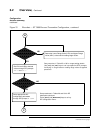
Table 20 Summary of Pressure Transmitter Configuration Parameters, continued
Configuration Data Setting or Selection
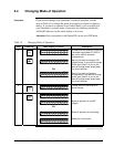
The following parameters are for transmitters in DE mode of operation only.
Mode of Output Signal
Indication
Any one of these selections based on control system information needs:
Single Range Sends the PV value corresponding to the
transmitter’s working range (PVw) to the
control system for display. For systems using
STDC card or STIMV IOP module (also called
STIM Smart Transmitter Interface Module).
Dual Range (STDC) Sends the PV values corresponding to the
transmitter’s full range (PVt) and working range
(PVw) measurements to the control system
for display. For systems using STDC card only.
Single Rng W/SV Sends PV value corresponding to the
transmitter’s working range (PVw) and
temperature value from the transmitter’s sensor
to the control system for display. For systems
using STDC card or STIMV IOP module.
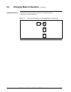
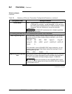
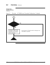
Message Format
Choose one of these broadcast types for data transmission to the digital
control system: Note that “DB” in following selection prompt stands for
“database”.
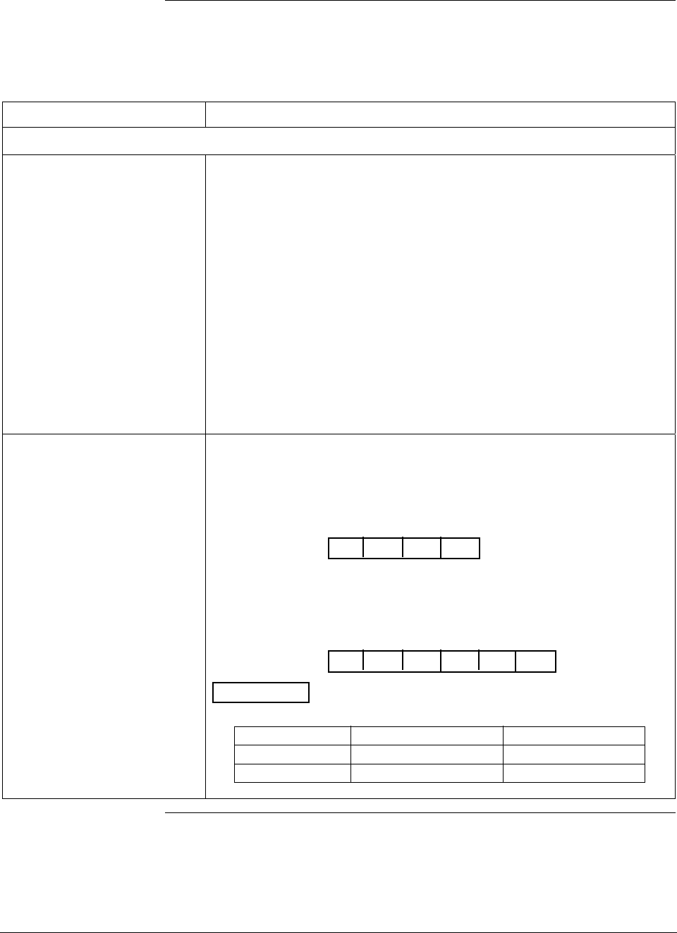
w/oDB (4 Byte) Byte 1 is output signal mode
Bytes 2 to 4 are PV value
FLAG PV PV PV
1234
w/DB (6 Byte) Byte 1 is output signal mode
Bytes 2 to 4 are PV value
Byte 5 is data type identifier (LRV, URV span, etc.)
Byte 6 is data being sent
FLAG PV PV PV
1234
ID DB
56
ATTENTION
The approximate rates of transmission in repeats per
second are:
Data 4 - Byte 6 - Byte
PV value 3 rpts/sec 2.5 rpts/sec
Temperature 1 rpt/2.5 sec 1 rpt/3 sec
Continued on next page