


6/08 ST 3000 Release 300 and SFC Model STS103 User’s Manual 65
6.2 Overview, Continued
What to configure,
continued
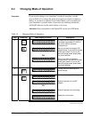
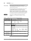
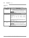
Table 20 Summary of Pressure Transmitter Configuration Parameters, continued
Configuration Data Setting or Selection
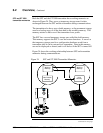
Failsafe Mode
NOTE: This parameter is valid only to select the failsafe action for the
STDC card in a controller - not the transmitter. If you are using
the STDC card to interface with the ST 3000 transmitter, contact
Honeywell Technical Assistance in using this parameter.
ATTENTION
An STIMV IOP module has built-in failsafe capabilities
and ignores this parameter.
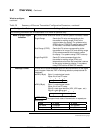
The following parameters are only for transmitters with optional Local Smart Meter.
Meter Engineering Units
If the transmitter is set for LINEAR output conformity, you can choose to
have the Local Smart Meter display pressure readings in one of these
engineering units:
“H2O_39F PSI MPa BAR Kg/cm^2 inHg_32F
mmHg_0C KPa mBAR g/cm^2 mmH2O_4C mH2O_4C
Custom %
If the transmitter is set for SQUARE ROOT output conformity, you can
choose to have the Local Smart Meter display flow readings in one of
these engineering units:
GPM GPH Custom %
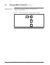
Engineering Units High and
Low
You can enter desired lower and upper (high) display limits to scale flow
(GPM, GPH) or Custom engineering units to represent the transmitter’s
0 to 100% output within the meter’s display range of ±19,990,000.
ATTENTION
When the transmitter is set to SQUARE ROOT output
conformity, the lower display limit for flow units (GPM, GPH) and Custom
unit must equal zero (0).
Continued on next page