


6/08 ST 3000 Release 300 and SFC Model STS103 User’s Manual 155
8.3 Changing Default Failsafe Direction
Background
Transmitters are shipped with a default failsafe direction of upscale.
This means that the transmitter’s output will be driven upscale
(maximum output) when the transmitter detects a critical status.
You can change the direction from upscale to downscale (minimum
output) by cutting jumper W1 on the Printed Wiring Assembly (PWA)
Analog and DE mode
differences
If your transmitter is operating in the analog mode, an upscale failsafe
action will drive the transmitter’s output to greater than 21 mA or a
downscale action will drive its output to less than 3.8 mA.
If your transmitter is operating in the DE mode, an upscale failsafe
action will cause the transmitter to generate a “+ infinity” digital signal,
or a downscale failsafe action will cause it to generate a “– infinity”
digital signal. The STIMV IOP module interprets either signal as “not a
number” and initiates its own configured failsafe action for the control
system. The STDC card initiates the failsafe mode configured through
the transmitter when either signal is generated.
ATTENTION
The failsafe direction display that you can access through the SFC only
shows the state of the failsafe jumper in the transmitter as it correlates to
analog transmitter operation. The failsafe action of the digital control
system may be configured to operate differently than indicated by the
state of the jumper in the transmitter.
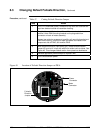
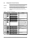
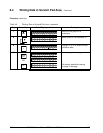
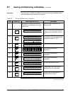
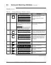
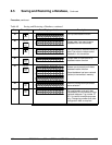
Procedure
The procedure in Table 47 outlines the steps for cutting the failsafe
direction jumper on the transmitter’s PWA. Figure 49 shows the
location of the failsafe direction jumper on the PWA of, Release 300
transmitters.
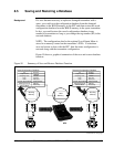
The nature of the integrated circuitry used in the transmitter’s PWA
makes it susceptible to damage by stray static discharges when it is
removed from the transmitter. Follow these tips to minimize chances of
static electricity damage when handling the PWA.
•
Never touch terminals, connectors, component leads, or circuits when
handling the PWA.
• When removing or installing the PWA, hold it by its edges or bracket
section only. If you must touch the PWA circuits, be sure you are
grounded by staying in contact with a grounded surface or wearing a
grounded wrist strap.
•
As soon as the PWA is removed from the transmitter, put it in an
electrically conductive bag or wrap it in aluminum foil to protect it.
Continued on next page