


6/08 ST 3000 Release 300 and SFC Model STS103 User’s Manual 133
7.6 Liquid Level Measurement - Vented Tank
Procedure
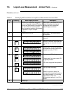
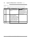
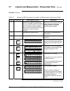
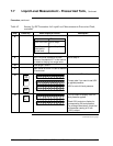
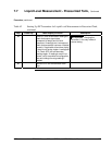
The procedure in Table 41 outlines the steps for starting up a differential
pressure (DP) type transmitter in a liquid level measurement application
for a vented tank with a dry reference leg. Refer to Figure 41 for the
piping arrangement identification and Figure 38 for typical SFC and
meter connections.
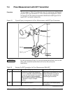
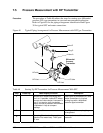
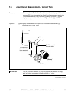
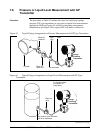
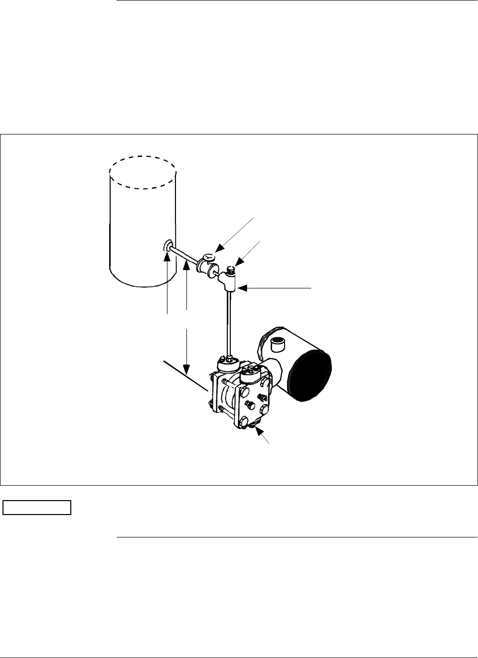
Figure 41 Typical Piping Arrangement for Liquid Level Measurement with DP Type
Transmitter and Vented Tank
Valve A
Plug C
LP Vent
Tap location at
the minimum level
to be measured
To HP connection
on meter body
Differential
Pressure
Transmitter
H
ATTENTION
For the procedure in Table 41, we are assuming that the tank is empty
and the piping arrangement includes a block-off valve.
Continued on next page