


ST 3000 Release 300 and SFC Model STS103 User’s Manual 6/08
132
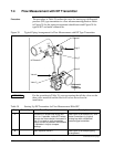
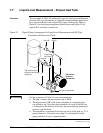
7.5 Pressure Measurement with DP Transmitter, Continued
Procedure, continued
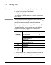
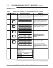
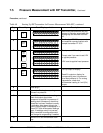
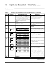
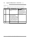
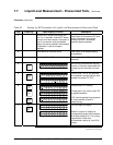
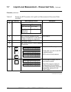
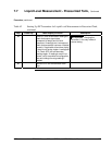
Table 40 Starting Up DP Transmitter for Pressure Measurement With SFC, continued
Step Press Key Read Display or Action Description
4
DE READ
A
ID
TA ON.G
?TRIPS SECURED?
Be sure any switches that may trip
alarms or interlocks associated with
analog loop are secured or turned
off.
5
NON-VOL
ENTER
(Yes)
TA ON.G
SFC WORKING.. .
LIN AG NO.DP T
P T3Ø11
Confirm that “TRIPS” are secured
and establish communications with
sample transmitter PT 3011
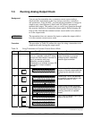
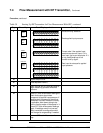
6
E
LRV
0%
SET
G
NON-VOL
ENTER
(Yes)
PTLRV 3Ø111
Ø
. ØØØØ PS I
PTLRV
RV
3Ø11
L
1
?SET
PTLRV 3Ø111
1
. 8315 PSI
Read present LRV setting.
Prompt asks if you want to set LRV
to applied pressure.
LRV is set to applied head pressure.
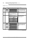
7
INPUT
J
OUT-
PUT
PTOUT 3Ø111P
FC WOSING.RK ..
%.Ø
PTOUT 3Ø111P
ØØØ
Call up output for display.
Read 0% output on display for
corresponding zero line pressure
plus head pressure H. For analog
transmission, check that
milliammeter reading is 4 mA (0%)
output.
8
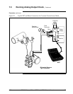
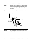
Close plug C
9
Open valve D to begin measuring
process line pressure.
10
Take SFC and milliammeter readings to
check that output signal does
correspond to applied line pressure. If
readings don’t correspond, check that
transmitter has been installed correctly.
If applicable, blow down piping to be
sure no foreign matter is entrapped in it.
Check SFC and milliammeter readings
again. If readings are still not correct,
verify transmitter’s configuration data
and change its range setting if needed.
11
Remove SFC and milliammeter from
loop.