


6/08 ST 3000 Release 300 and SFC Model STS103 User’s Manual 45
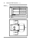
4.4 Wiring ST 3000 Transmitter, Continued
Wiring connections
and installation
drawings
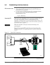
The procedure in Table 16 shows the steps for connecting power to the
transmitter. For loop wiring and external wiring diagrams, refer to the
installation drawings presented in Section 13. Detailed drawings are
provided for transmitter installation in non-intrinsically safe areas and
for intrinsically safe loops in hazardous area locations. If you are using
the transmitter with Honeywell’s TPS system, see the previous TPS
reference.
ATTENTION
• All wiring must comply with local codes, regulations, and
ordinances.
• If you will be using the transmitter in a hazardous area, be sure to
review the hazardous location reference data included in Appendix
D of this manual before operating the transmitter.
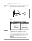
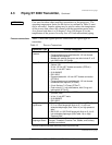
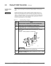
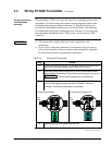
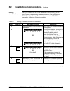
Table 16 Wiring the Transmitter
Step Action
1
Loosen end-cap lock using a 1.5 mm allen wrench and remove end-
cap cover from terminal block end of electronics housing.
2
Feed loop power leads through one of conduit entrances on either
side of electronics housing. Plug whichever entrance you do not use.
ATTENTION
The transmitter accepts up to 16 AWG wire.
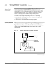
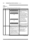
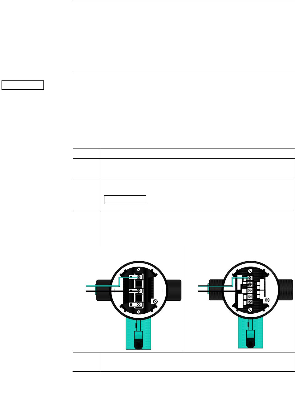
3
Observing polarity, connect positive loop power lead to SIGNAL +
terminal and negative loop power lead to SIGNAL – terminal.
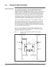
Example – Connecting loop power to transmitter.
3-screw terminal block
-
S
I
G
N
A
L
+
+
-
T
E
S
T
+
-
Loop
Power
5-screw terminal (option LP)
+
+
-
-
L
-
S
I
G
N
A
L
M
E
T
E
R
T
E
S
T
S
I
G
N
A
L
-
+
+
-
+
-
Loop
Power
4
Replace end-cap, and tighten end-cap lock.
Continued on next page