


6/08 ST 3000 Release 300 and SFC Model STS103 User’s Manual 241
B.1 Possible Solutions/Methods, Continued
Mechanical
(diaphragm) seals,
continued
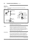
You must be careful to specify large enough diaphragms to accommodate
expansion and contraction of the fill fluid under varying temperatures
without overextending the diaphragm into its stiff area. In general,
conventional diaphragm seals are satisfactory for pressure ranges above
approximately 75 psig with special large diameter elements required for
low pressure or differential pressure measurements.
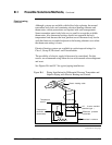
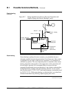
You can lag (insulate) impulse lines and diaphragm seals with the process
piping, but this practice is only common with liquid level applications
involving highly viscous materials unsuitable for 1/2-inch impulse lines.
Use a tank-mounted flanged seal in such installations. Otherwise, it is
more desirable to keep the capillary lengths short, the transmitter
accessible for maintenance, and (for flow applications) the normal 3-valve
manifold assembly close to the transmitter for normal service checks.
Thus, the impulse lines, valving and diaphragm seals with 1/2-inch
connections would be electrically or steam traced, with high temperature
steam permitted without damage to the transmitter. See Figures B-4 and
B-5 for typical piping layouts.
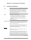
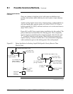
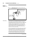
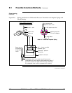
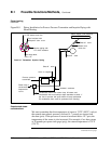
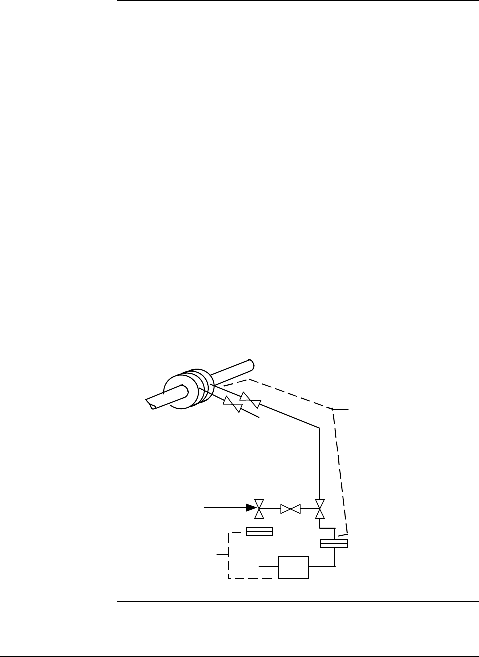
Figure B-4 Piping Installation for Differential Pressure Transmitter with
Metal Diaphragm Seals.
The impulse piping, 3-valve
manifold, and upper flanges
of the metal diaphragm seals
must be insulated and, where
required, also heated by
electric or steam.
1/2" , 3-valve manifold
(standard type with
suitable temperature rating)
Differential pressure
transmitter with metal
diaphragm seals
Continued on next page