6/08 ST 3000 Release 300 and SFC Model STS103 User’s Manual 257
D.1 North American Classification of Hazardous
Locations,
Continued
Entity Concept
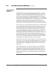
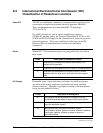
Under entity requirements, the concept allows interconnection of
intrinsically safe apparatus to associated apparatus, not specifically
examined in such combination. The criteria for interconnection is that the
voltage (Vmax ) and current (Imax ), which intrinsically safe apparatus
can receive and remain intrinsically safe, considering faults, must be
equal to or greater than the voltage (Voc or Vt ) and current (Isc or It )
levels which can be delivered by the associated apparatus, considering
faults and applicable factors. In addition, the maximum unprotected
capacitance (Ci ) and inductance (Li ) of the intrinsically safe apparatus,
including interconnecting wiring, must be less than or equal to the
capacitance (Ca ) and inductance (La ) which can be safely connected to
the associated apparatus. If these criteria are met, then the combination
may be connected and remain intrinsically safe. Both FMRC and CSA
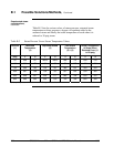
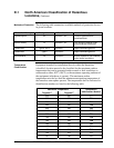
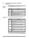
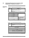
define the entity parameters in Tables D-1 and D-2.
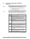
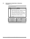
Table D-1 Factory Mutual (FM) Entity Parameters
Code Description
1C Factory Mutual (FM) Approval
• Explosionproof for Class I, Division 1, Groups A, B, C & D. Dust-
Ignitionproof for Class II, Division 1, Groups E, F & G. Suitable
for Class III, Division 1. Conduit seals required within 18” of
enclosure, Group A only.
• Intrinsically Safe for use in Class I, Division 1, Groups A, B, C &
D; Class II, Division 1, Groups E, F & G; Class III, Division 1, T4
at 40°C, T3A at 93°C maximum ambient, when connected in
accordance with Honeywell drawing 51204241.
• Nonincendive for use in Class I, Division 2, Groups A, B, C & D;
Suitable for Classes II & III, Division 2, Groups F & G, T4 at 93°C
maximum ambient, hazardous locations. 42 Vdc max.
• Environmental: Indoor & outdoor hazardous locations (NEMA 4X).
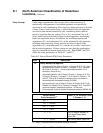
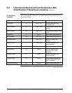
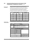
Intrinsic Safety
Entity Parameters
(1)
Class I, II, III, Divisions 1 and
2, Groups A - G
V
Max
≤
42.4 V
I
Max
= 225 mA
P
Max
= 1.2 W
C
i
= 4.2 nF
L
i
= 0 With no integral indicator, or
with integral Smart Meter,
option SM.
L
i
=
150 μH
With Analog Meter, option ME.
(1) Install in accordance with Honeywell drawing 51204241.


