


6/08 ST 3000 Release 300 and SFC Model STS103 User’s Manual 137
7.7 Liquid Level Measurement - Pressurized Tank, Continued
Procedure, continued
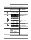
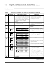
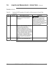
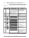
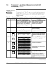
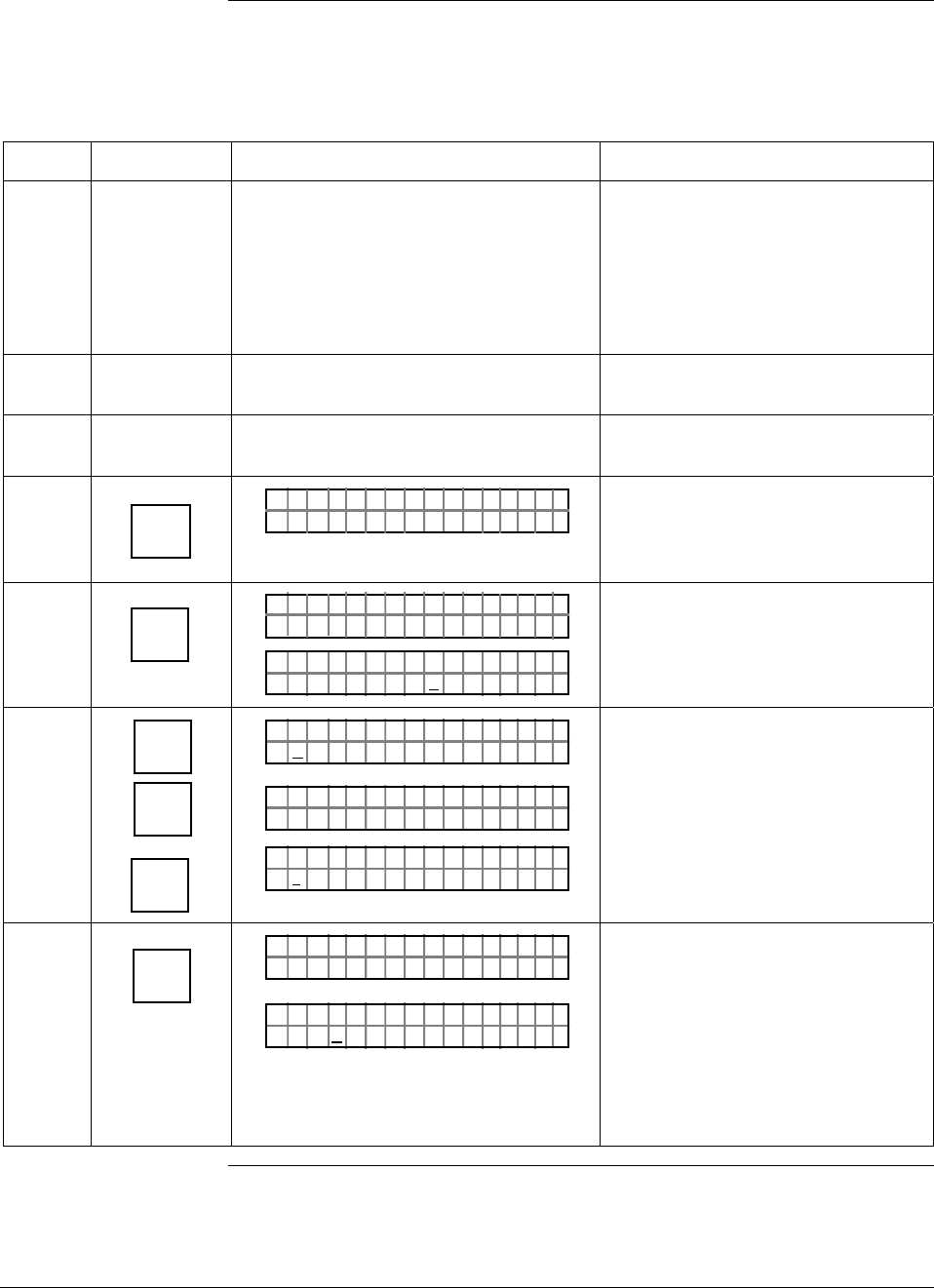
Table 42 Starting Up DP Transmitter for Liquid Level Measurement in Pressurized Tank
Step Press Key Read Display or Action Description
1
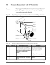
Connect SFC across loop wiring and
turn it on. If possible, locate SFC where
you can also view receiver instrument in
loop. If you want to verify transmitter
output, connect a precision milliammeter
or voltmeter in loop to compare
readings.
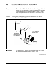
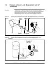
See Figure 38 for sample SFC and
meter connections in a typical
analog loop with a differential
pressure type transmitter.
2
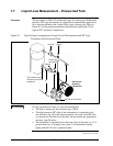
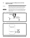
Close block-off valves A and B. See Figure 42 for sample piping
arrangement.
3
Open plugs C and D. Allow system to stabilize at head
pressure.
4
DE READ
A
ID
TA ON.G
?TRIPS SECURED?
Be sure any switches that may trip
alarms or interlocks associated with
analog loop are secured or turned
off.
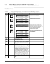
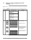
5
NON-VOL
ENTER
(Yes)
TA ON.G
SFC WORKING.. .
LIN AG NO.DP T
P T3Ø11
Confirm that “TRIPS” are secured
and establish communications with
sample transmitter PT 3011
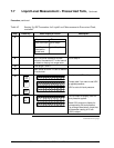
6
E
LRV
0%
SET
G
NON-VOL
ENTER
(Yes)
PTLRV 3Ø111
Ø
. ØØØØ
"
H2O
_
39F
PTLRV
RV
3Ø11
L
1
?SET
PTLRV 3Ø111
1
.Ø5 32
"
H2O
_
39F
Read present LRV setting.
Prompt asks if you want to set LRV
to applied pressure.
LRV is set to applied head pressure
H
1
times density of liquid in
reference leg.
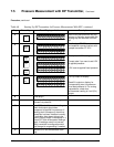
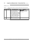
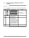
7
INPUT
J
OUT-
PUT
PTOUT 3Ø111P
FC WOSING.RK ..
%.Ø
PTOUT 3Ø111P
ØØØ
Call up output for display.
Read 0% output on display for
corresponding empty tank pressure
plus head pressure H
1
. For analog
transmission, check that
milliammeter reading is 4 mA (0%)
output.
Continued on next page