


ST 3000 Release 300 and SFC Model STS103 User’s Manual 6/08
136
7.7 Liquid Level Measurement - Pressurized Tank
Procedure
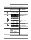
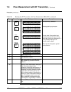
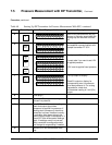
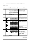
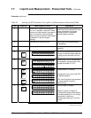
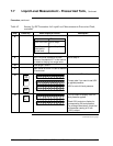
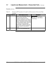
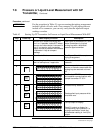
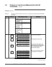
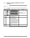
The procedure in Table 42 outlines the steps for starting up a differential
pressure (DP) type transmitter in a liquid level measurement application
for a pressurized tank with a liquid-filled (wet) reference leg. Refer to
Figure 42 for the piping arrangement identification and Figure 38 for
typical SFC and meter connections.
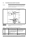
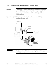
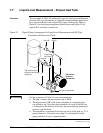
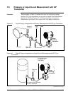
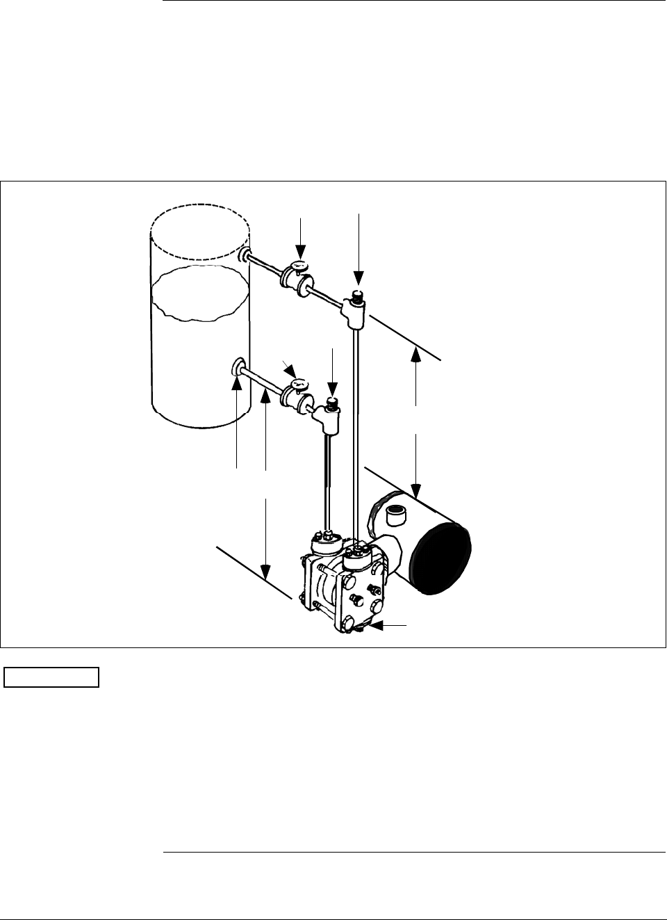
Figure 42 Typical Piping Arrangement for Liquid Level Measurement with DP Type
Transmitter and Pressurized Tank
Valve A
Plug C at
zero level
Tap location at the
minimum level to be
measured
HP side of transmitter
Differential
Pressure
Transmitter
h
H
1
Valve B
Plug D
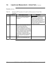
ATTENTION
For the procedure in Table 42, we are assuming that:
•
The tank is empty and the reference leg is filled.
• The high pressure (HP) side of the transmitter is connected to the
wet reference leg. Note that the transmitter will work if the HP side
is connected to the bottom of the tank, but not within the guaranteed
accuracy specifications.
•
The transmitter is mounted below the zero level of the tank, so “h” is
greater than zero. If h equals zero, plug C is eliminated from the
piping and the LP vent is opened instead.
Continued on next page