


6/08 ST 3000 Release 300 and SFC Model STS103 User’s Manual 43
4.4 Wiring ST 3000 Transmitter
Summary
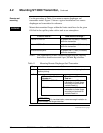
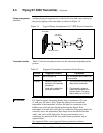
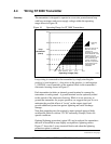
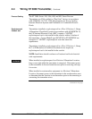
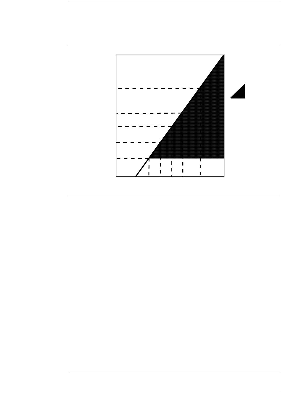
The transmitter is designed to operate in a two-wire power/current loop
with loop resistance and power supply voltage within the operating
range shown in Figure 16.
Figure 16 Operating Range for ST 3000 Transmitters.
0 10.8 16.28 20.63 25 28.3 37.0 42.4
250
450
650
800
1200
1440
Operating Voltage (Vdc)
= Operating
Area
NOTE: A minimum of
250 0hms of loop
resistance is
necessary to support
communications. Loop
resistance equals
barrier resistance plus
wire resistance plus
receiver resistance.
Also 45 volt operation
is permitted if not an
intrinsically safe
installation.
Loop
Resistance
(ohms)
21012
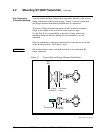
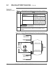
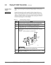
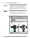
Loop wiring is connected to the transmitter by simply attaching the
positive (+) and negative (–) loop wires to the positive (+) and negative
(–) SIGNAL screw terminals on the terminal block in the transmitter’s
electronics housing shown in Figure 17.
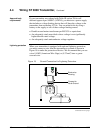
Each transmitter includes an internal ground terminal to connect the
transmitter to earth ground. A ground terminal can be optionally added
to the outside of the electronics housing. While it is not necessary to
ground the transmitter for proper operation, we suggest that you do so to
minimize the possible effects of “noise” on the output signal and
provide additional protection against lightning and static discharge
damage.
Note that grounding may be required to meet optional approval body
certification. Refer to section 3.2 CE Conformity (Europe) Notice for
special conditions.
Optional lightning protection (option LP) can be ordered for transmitters
that will be installed in areas highly susceptible to lightning strikes.
Figure 17 shows the 5-screw terminal block used when the lightning
protection option is ordered.
Continued on next page