


6/08 ST 3000 Release 300 and SFC Model STS103 User’s Manual 33
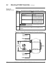
4.2 Mounting ST 3000 Transmitter, Continued
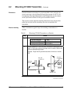
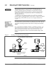
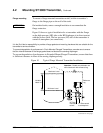
Flange mounting
To mount a flange mounted transmitter model, bolt the transmitter’s
flange to the flange pipe on the wall of the tank.
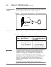
ATTENTION
On insulated tanks, remove enough insulation to accommodate the
flange extension.
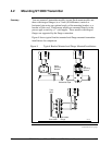
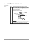
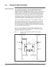
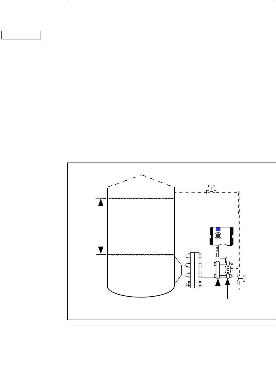
Figure 10 shows a typical installation for a transmitter with the flange
on the high pressure (HP) side so the HP diaphragm is in direct contact
with the process fluid. The low pressure (LP) side of the transmitter is
vented to atmosphere (no connection).
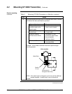
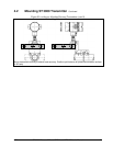
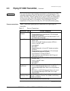
It is the End User’s responsibility to provide a flange gasket and mounting hardware that are suitable for the
transmitter’s service condition.
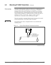
To prevent degradation of performance in Flush-Mounted Flanged Transmitters, exercise care to ensure
that the internal diameter of the flange gasket does not obstruct the sensing diaphragm.
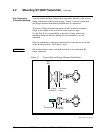
To prevent degradation of performance in Extended Mount Flanged Transmitters, ensure that there
is sufficient clearance in front of the sensing diaphragm body.
Figure 10 Typical Flange Mounted Transmitter Installation
Variable
Head H1
Reference
Leg
Attention: Dotted area indicates use
with closed tank with reference leg.
LP Side vented
to atmosphere
HP Side
mounted
to tank
Minimum Level
Maximum Level
Continued on next page