


6/08 ST 3000 Release 300 and SFC Model STS103 User’s Manual 145
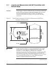
7.10 Pressure Measurement with AP Transmitter
Procedure The procedure in Table 44 outlines the steps for starting up an absolute
pressure (AP) type transmitter in a pressure measurement application.
Refer to Figure 47 for the piping arrangement identification and Figure
38 for typical SFC and meter connections.
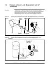
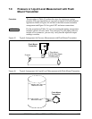
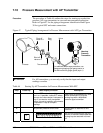
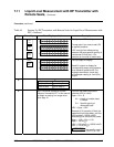
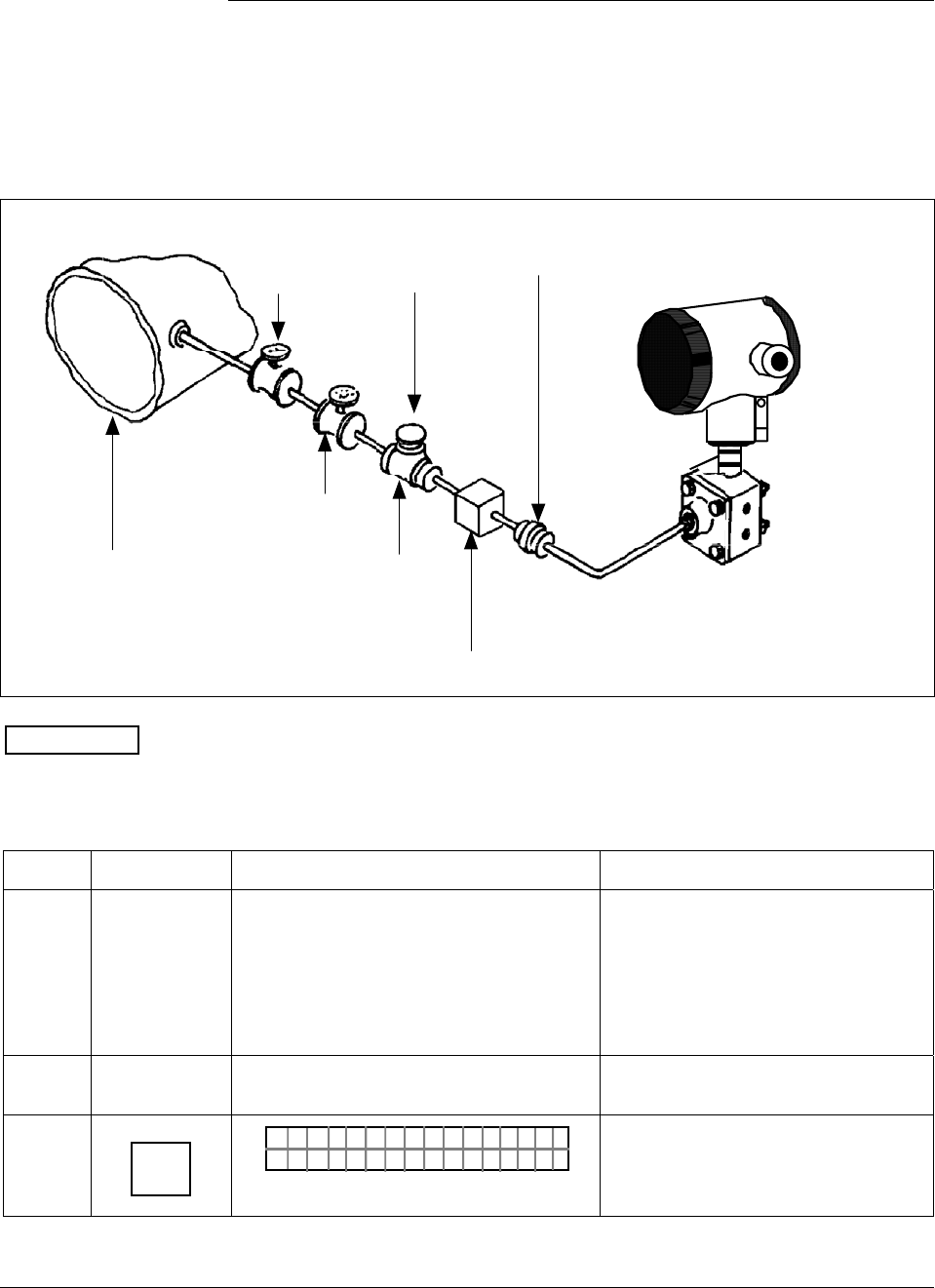
Figure 47 Typical Piping Arrangement for Pressure Measurement with AP Type Transmitter.
Shut-off
valve no.2
Absolute
Pressure
Transmitter
Union
Shut-off
valve no.1
Pipe
Plug
Process
Tee connector
For additional overrrange protection, use
Sprague engineering type gauge saver or
Fairchild model 95 gauge guard (style 1)
ATTENTION
For AP transmitters, you can only verify that the input and output
readings correlate.
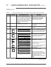
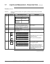
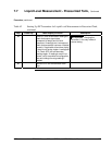
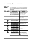
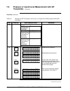
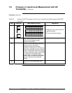
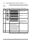
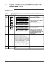
Table 44 Starting Up AP Transmitter for Pressure Measurement With SFC
Step Press Key Read Display or Action Description
1
Connect SFC across loop wiring and
turn it on. If possible, locate SFC where
you can also view receiver instrument in
loop. If you want to verify transmitter
output, connect a precision milliammeter
or voltmeter in loop to compare
readings.
See Figure 38 for sample SFC and
meter connections in a typical
analog loop with a differential
pressure type transmitter.
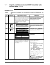
2
Set process pressure to zero level Allow system to stabilize at zero
pressure.
3
DE READ
A
ID
TA ON.G
?TRIPS SECURED?
Be sure any switches that may trip
alarms or interlocks associated with
analog loop are secured or turned
off.
Continued on next page