


240 ST 3000 Release 300 and SFC Model STS103 User’s Manual 6/08
B.1 Possible Solutions/Methods, Continued
Gas applications,
continued
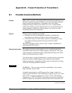
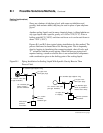
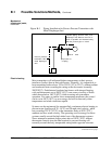
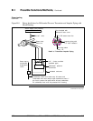
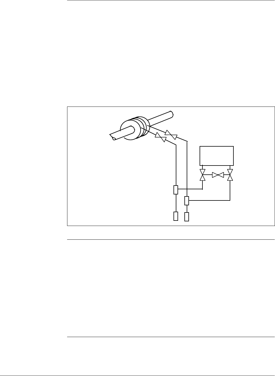
point in the transmitter meter body and the piping is sloped downward at
least one inch per foot. (Side-connected transmitters with vent-drains at a
lower point in the meter body must be regularly checked to assure
condensate removal.) If the transmitter is located below the process taps
(not recommended), piping must still run downward from the transmitter
to the drain point and then up to the process as shown in Figure B-3.
Steam or electric heating of the drain point will prevent pipe rupture due
to freezing.
Figure B-3 Piping Installation for Gas Flow.
Transmitter
Mechanical
(diaphragm) seals
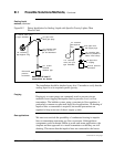
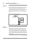
Diaphragm seals on the impulse lines provide the most expensive, yet
broadest application of all the methods. Similar in principle to the liquid
seals, diaphragm seals eliminate the possibility of seal liquid carry-over
into the process fluid. This eliminates the need for periodic maintenance
checks to assure full and equal liquid seal legs. Welded diaphragm seals
with special fills permit temperatures from –34° to 600°F (–36° to 315°C)
at the process interface which can therefore be steam or electrically heated
to assure viscosity of tars and similar high-freezing point fluids under the
coldest conditions.
Continued on next page