


ST 3000 Release 300 and SFC Model STS103 User’s Manual 6/08
144
7.9 Pressure or Liquid Level Measurement with Flush
Mount Transmitter
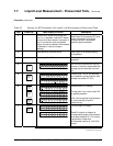
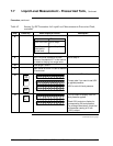
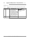
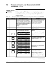
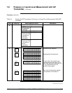
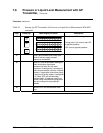
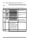
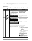
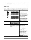
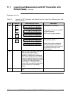
Procedure The procedure in Table 43 outlines the steps for starting up a gauge
pressure (GP) type transmitter in a pressure or liquid level measurement
application. Refer to Figures 45 and 46 for the flush mount transmitter
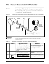
arrangement and Figure 38 for typical SFC and meter connections.
ATTENTION
For the procedure in Table 43, we are assuming that piping arrangement
includes a block-off valve and a Tee-connector. If your piping does not
include a Tee-connector, you can only verify that the input and output
readings correlate.
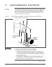
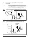
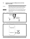
Figure 45 Typical Arrangement for Pressure Measurement with Flush Mount Transmitter
Process
Flush Mount
Transmitter
1" Pipe Mount -
316 SS Weld Nipple
(standard option)
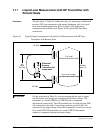
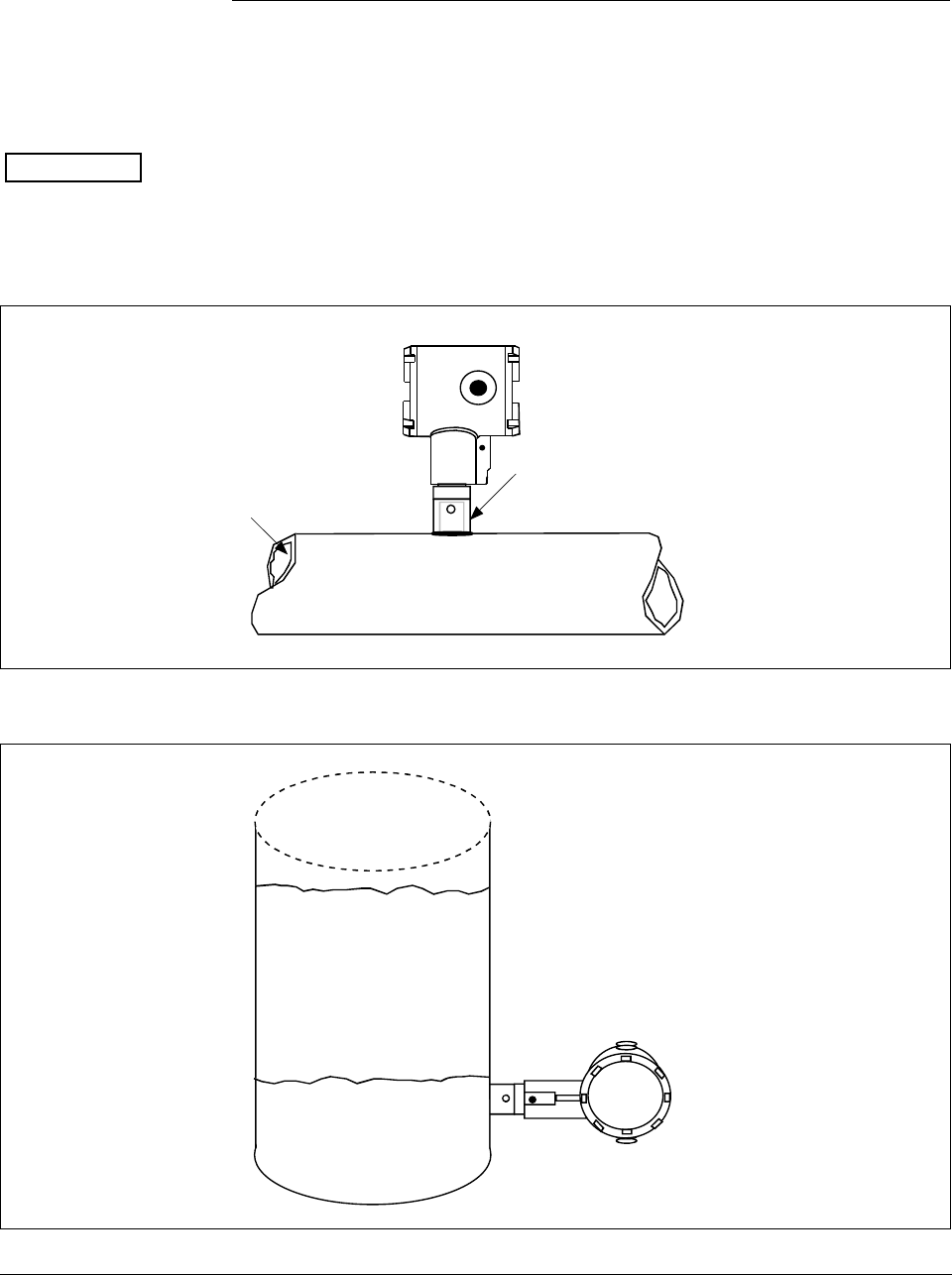
Figure 46 Typical Arrangement for Liquid Level Measurement with Flush Mount Transmitter
Flush Mount
Transmitter
Maximum Level
Minimum Level