


ST 3000 Release 300 and SFC Model STS103 User’s Manual 6/08
104
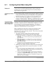
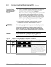
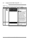
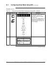
6.12 Configuring Smart Meter Using Pushbuttons, Continued
Transmitter Output
Conformity and Smart
Meter Configuration
Normally when using a differential type transmitter, you can select the
transmitter’s output to represent a straight linear calculation or a square
root calculation for flow measurement applications. This linear or
square root output parameter selection is called output conformity or
output form. (See Subsection 6.4 for more details.)
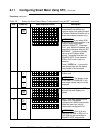
When configuring the smart meter to display the transmitter output
measurement, there are certain rules to keep in mind which are
dependent on the output conformity selection. These rules are described
in the following paragraphs.
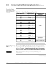
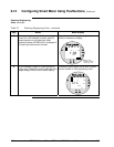
1. The output conformity setting of the transmitter restricts the
engineering units you can select for the smart meter display.
• When the transmitter is configured for an output conformity of
LINEAR, you can select only pressure type engineering units.
(See Table 32.)
• When the transmitter is configured for an output conformity of
SQUARE ROOT, you can select only flow type engineering
units GPM and GPH.
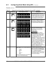
• The percent and custom engineering units can be selected
regardless of output conformity configuration.
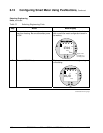
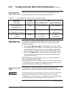
2. Additionally, the output conformity setting restricts the setting of the
lower and upper display limits to represent transmitter’s 0 to 100%
output.
• If you select pressure type engineering units, you cannot set the
lower or upper display limits. These values are automatically set
when you select the engineering units.
• You can set only the upper display limit when the transmitter is
configured for SQUARE ROOT output conformity. The lower
display limit is fixed at zero (0) for a transmitter in square root
mode and cannot be changed.
• You can set both the lower and upper display limits when you
have selected custom engineering units (EUF) and the
transmitter output conformity is set to LINEAR.
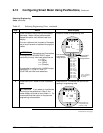
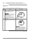
When setting the lower and upper display limits, if you let either the
lower or upper display limit setting time out (after thirty seconds), the
meter will discard the newly set values and will revert to its previous
settings. The meter forces you to set both limits by automatically
initiating the next limit setting, either lower or upper, depending upon
which limit you set first.
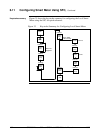
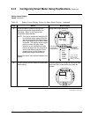
3.
If you change the transmitter’s output conformity, you must
reconfigure the Local Smart meter as outlined in Tables 33 to 36.
Continued on next page