DEFINITY Enterprise Communications Server Release 7
Maintenance for R7r
555-230-126
Issue 4
June 1999
Maintenance Object Repair Procedures
9-668DS1 CONV-BD
9
!
WARNING:
Do not power down a Switch Node carrier to replace a circuit pack.
!
WARNING:
Replacing a Switch Node Interface, Switch Node Clock, Expansion
Interface or DS1 Converter circuit pack on a simplex system disrupts
service. The service effect can range from outage of a single EPN to outage
of the entire system.
!
WARNING:
A DS1 Converter Complex must consist of two TN574 boards or two
TN1654 boards. A TN574 cannot be combined with a TN1654 in the same
DS1 CONV Complex.
!
WARNING:
The two DS1 CONV boards, TN1654 and TN574, use unique “Y” cables that
are incompatible with each other.
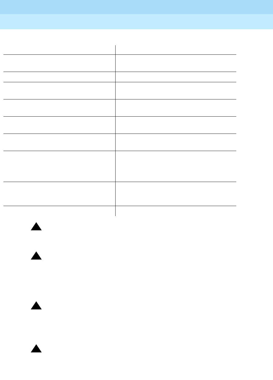
Steps Comments
Enter
status pnc
Verify that the component to be replaced is
on the standby PNC.
Enter
busyout pnc
Enter
busyout board
UUCSS UUCSS represents the cabinet-carrier-slot
address of the circuit pack to be replaced.
Replace the circuit pack with the same
DS1 CONV board type.
Enter
release board
UUCSS
CAUTION:
Do not busyout any Expansion
Interface circuit pack after this point.
Enter
test alarms long clear
for
category
exp-intf
Wait 5 minutes for SNI-BD, SNI-PEER,
FIBER-LK, and DS1C-BD alarms to clear,
or enter
clear firmware counters
<a-pnc or b-pnc>
Use the letter designation of the pnc which
holds the replaced component (the standby
pnc).
Enter
status pnc
If either PNC state-of-health is not
"functional", consult the PNC-DUP section of
the Maintenance Manual.
Enter
release pnc


