


Performance Tests
Performance Verification
4Ć28
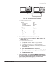
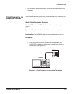
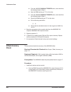
b. Set frequency counter controls:
CHANNEL A
Termination 50ĂΩ
Slope Negative
Attenuation X5
Coupling DC
FREQ A
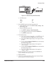
2. Set AWG2005 controls and select the waveform:
a. Initialize AWG2005 controls: Push UTILITY!Misc!Config...!ReĆ
set to Factory!O.K.
b. Select the waveform file:
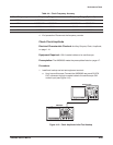
H Push SETUP!Waveform Sequence, if necessary, to select a
waveform file for CH1. Waveform Sequence toggles between the
CH1 files (upper list) and the CH2 files (lower list).
H Turn the general purpose knob to select the CLK_FREQ.WFM
file.
H Push ENTER to select the file.
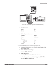
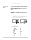
3. Check clock frequency accuracy:
a. Check clock frequency accuracy at current clock frequency setting:
Check that the frequency counter reading falls between
19.9999ĂMHz and 20.001ĂMHz (between 19.9999 MHz and
20.0001 MHz for the instrument with Option 05).
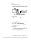
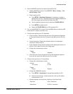
b. Check clock frequency accuracy for different clock frequency setĆ
tings:
H Select Clock from the bottom of the SETUP menu.
H Push Source from the side menu to highlight Internal.
H Select Internal Clock from the side menu.
H Turn the general purpose knob (or press the numeric and units
keys, and push ENTER) to select the first clock frequency listed
in Table 4Ć4.
H Check that the frequency counter reading is within the frequenĆ
cy range listed in the table for the clock frequency setting (refer
to right column in the table for the instrument with Option 05).
H Repeat this step for each clock frequency and frequency range
listed in Table 4Ć4.