


Instructions for Operation
Operating Information
2Ć18
Step Ċ When a trigger signal is received, the Step:1 waveform for
each channel is output once. When the next trigger signal is reĆ
ceived, the Step:2 waveform is output (once). When the next trigger
signal is received while waveform output is in progress, output stops
after the end point of that waveform and then the waveform for the
next step is output.
3. Set the trigger (gate) conditions for the external trigger (gate) source.
The external trigger (gate) signal is input from the TRIGGER INPUT
connector on the front panel. The input impedance is 10 kW and the
maximum input voltage is "10 V.
When an operating mode other than Cont is selected, the AWG2005
displays a side menu for selecting the trigger (gate) conditions for
the external trigger (gate) source. The following describes each of
these items.
H
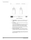
Slope Ċ This item sets the slope for external trigger signals. To
select a positive or negative slope, push the side menu Slope butĆ
ton. For a positive slope, the AWG2005 applies the trigger at the
rising edge of the external trigger signal; for a negative slope, the
trigger is applied at the falling edge of the external trigger signal.
H Polarity (Gated Mode) Ċ This item sets the polarity for the gate
that outputs the waveform or sequence based on the level of the
external gate signal. To set the polarity, push the side menu Polarity
button. For a positive polarity, the AWG2005 outputs the waveform
or sequence waveform while the gate signal level is higher than the
gate level parameter set with the side menu Level item. For negative
polarity, waveform output occurs while the gate signal level is lower.
H Level Ċ This item sets the external trigger (gate) signal level. To set
this parameter push the side menu Level button, then use the nuĆ
meric keys or the general purpose knob to change the value. The
trigger (gate) level can be set in steps of 0.1ĂV within the range from
-5.0ĂV to 5.0ĂV.