


Performance Tests
Performance Verification
4Ć18
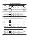
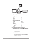
Trigger
Source CH1
b. Apply gate signal: Turn function generator output on.
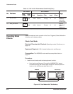
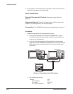
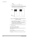
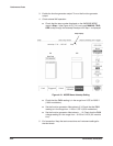
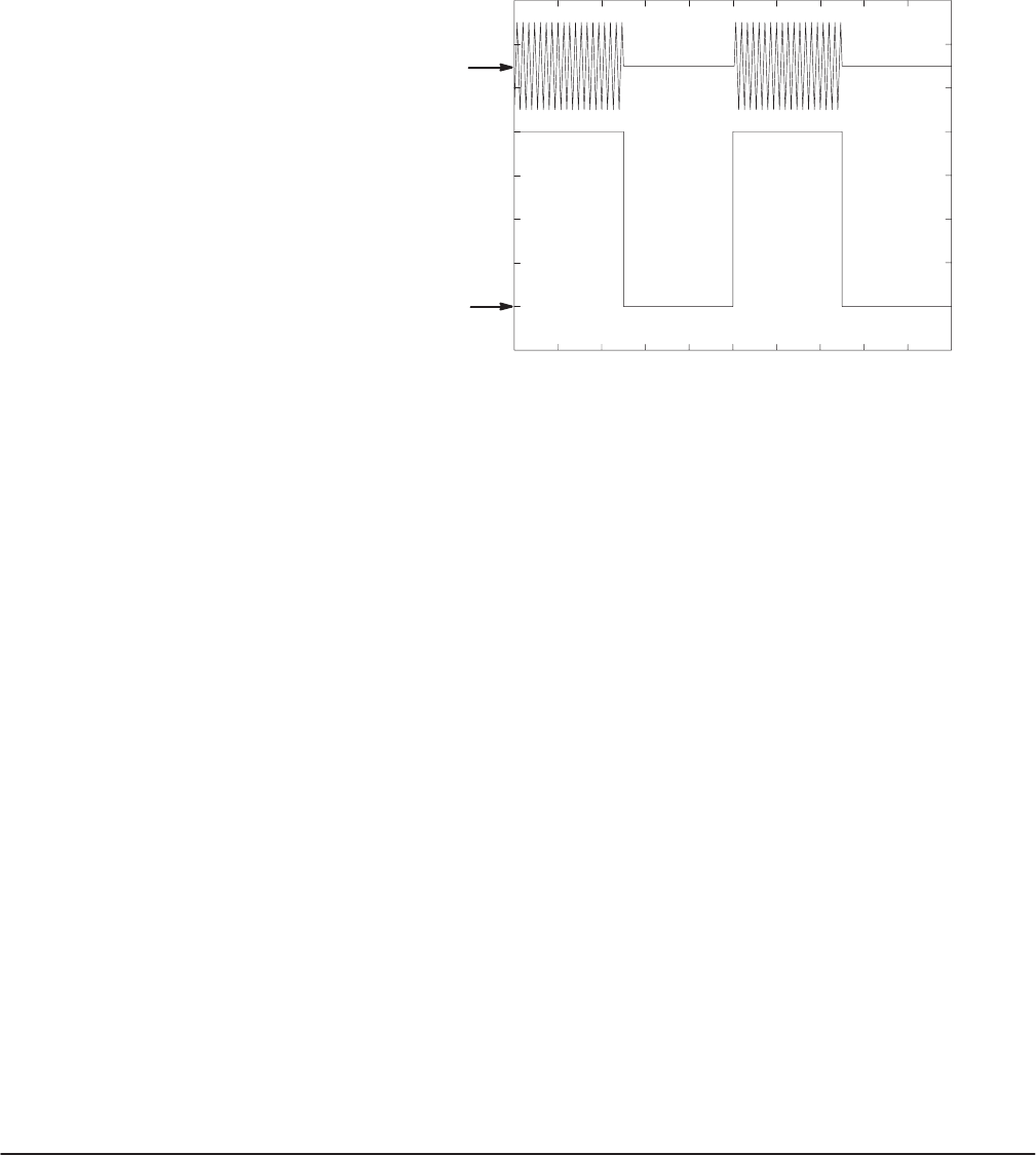
c. Check gated mode with positive gate signal: Check that the oscilloĆ
scope displays a sine wave while the function generator gate signal
level is in upper portion of the display (see Figure 4Ć6).
Gate
Signal
Waveform
Output
CH2
CH1
Figure 4Ć6:ăRelationship between 1 Volt or Greater Gate Signal and
Waveform Output Signal
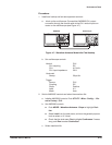
d. Change the AWG2005 trigger polarity to negative: Push MODE!PoĆ
larity to change the polarity to Negative.
e. Check gated mode with a negative gate signal: Check that the
oscilloscope displays a sine wave while the function generator gate
signal level is in the lower portion of the display.
6. End procedure: Turn the function generator output off and disconnect
the function generator.
Check Waveform Advance Mode
Electrical Characteristic Checked: Operating modes, Waveform AdĆ
vance, on pageĂ1Ć5.
Equipment Required: A 50ĂΩ coaxial cable and an oscilloscope.
Prerequisites: The AWG2005 meets the prerequisites listed on page 4Ć7.