


Performance Tests
Performance Verification
4Ć48
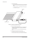
a. Check the signal levels:
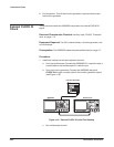
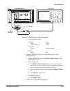
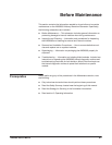
H Contact the oscilloscope probe to the pins on 2 X13 header (see
Figure 4Ć22). Check that the oscilloscope display shows these
signals:
H Data signals D0ĆD11 and CLK (Clock) are TTL level output.
H All other pins are ground.
Digital Data Out Cable
D1
D0
GND
CLK
GND
2X13 Header
D11
Figure 4Ć22:ăOutput Pins on the Digital Data Out Cable
4. Check the CH2 digital data output signals:
a. Change connection: Change the connection for the digital data out
cable from CH1 DIGITAL DATA OUT connector to CH2 DIGITAL
DATA OUT connector.
b. Repeat the step 2 and 3 to check the CH2 digital data output sigĆ
nals.
5. Turn off equipment output and disconnect test hookup:
a. Disable power supply output: Turn off power supply output.
b. Remove connections: Disconnect all connections to the AWG2005.