


Removal and Installation Procedures
Maintenance
6Ć40
2. Remove fan and fan frame: Do the Fan and Fan Frame procedure on
page 6Ć33.
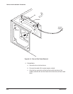
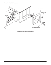
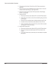
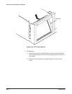
3. Orient instrument: Set the AWG2005 with the bottom down on the work
surface and the back facing you (see Figure 6Ć18).
4. Remove the power supply module: Do the procedure, Power Supply
Module, on page 6Ć38.
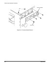
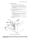
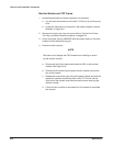
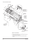
5. Remove AC inlet:
a. Disconnect the interconnect cable at CN1 on the AUX Power board.
b. Using a
5
@
16
Ćinch nut driver, remove the nut attaching the ground wire
to the chassis.
c. Remove the two insulating tubes of cables attached to the AC inlet.
d. Unsolder the three interconnect cables attached to the AC inlet.
e. Using a screwdriver with a size TĆ15 Torx tip, remove the two screws
securing the AC inlet to the chassis.
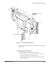
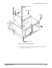
6. Remove AUX Power board:
a. Disconnect the interconnect cable at CN2 on the AUX Power board.
b. Remove the three screws attaching the AUX Power board to the
chassis.
c. Lift the AUX Power board up and away from the chassis to complete
the removal.